Featured Post

Beolover SyncDrive: DC Platter Motor Replacement for Beogram 4002 and 4004 (Type 551x and 552x)

Late Beogram 4002 and the 4004 (Types 551x and 552x), which have DC platter motors instead of the earlier synchronous AC motors usually suff...

Showing posts with label actuator. Show all posts

Friday, February 11, 2022

Beomaster 4400 Type 2419: Repairing the Off Switch

I received some parts I had ordered for the current Beomaster projects I have on my workbenches.

For this Beomaster 4400 Off Switch problem I showed in the last post how the switch assembly mechanics were not functioning correctly because of a worn plastic post on the actuator.


The plastic post on the actuator presses against a metal lever to release any source switches that have been engaged. The 2 mm post was not doing its job due to wear.

My options were to find a donor Off switch from a Beomaster 3000, 4000 or 4400 that have that same type of Off switch or to repair the one that I have.

Martin Olsen is sending me a replacement Off switch that he happened to have so that option will be available.  In the meantime I implemented the following repair.

Using a 2 mm inner diameter and 3 mm outer diameter tube of PTSE, I fashioned an outer ring on the original post. That was epoxied in place but I don't fully trust that to hold over long term actuating of the Off switch. So I added an M1 x 4 mm screw and washer to lock everything down.

For the mounting of the screw I originally thought I could use a longer screw and attach an M1 nut to hold it.  However, the location of the plastic actuator post is directly over a plastic support rib of the actuator so there was no room.

I opted for drilling a tiny hole through the actuator post into the plastic just over 4 mm deep.
The screw was then threaded into place to verify the fit.

That worked quite well so I permanently installed the screw with epoxy and an M1 washer.


The new actuator post is now a little larger in diameter than the original.
I trimmed down the edge of the PTFE ring that will make contact with the metal lever using a sharp razor blade. That makes the area where contact with the lever is the correct size to move the lever properly.  Too little, as when the post was worn, results in the lever not moving far enough.  Too much prevents the lever from returning to a position where switches can engage and lock.

After reinstalling the Off switch into the Beomaster 4400 switch assembly it is working properly again.
In the photos below you can see how the actuator post makes contact with the switch assembly control lever.


As the Off switch actuator moves across the bulge of the metal control lever, the lever momentarily presses the switch assembly release bar and any selected source switches become disengaged.

While I have the Beomaster switch assemble out I removed and opened up the phono (PH) switch to see what the contacts look like.  On a previous Beomaster 4400 restoration the source switches later became inconsistent in their ability to route the audio signals when selected.  The selected source would work for a while but eventually, one channel would drop out.  Recycling the source selection switches remedies the problem but it always returns.

Looking at the inside of one the the source selection switches I can see a possible reason why.


The actuator piece has spring contacts that slide across a set of fixed contacts to make up the switch.
You can see oxidation in the photo on the fixed contacts.  The spring contacts have some oxidation as well. 

If there is enough oxidation on the contacts then just spraying some Deoxit into the switch and operating it will probably not be enough to make it reliable again.

In this case I have completely disassembled the switch where I can scrub the contacts with an abrasive cleaner (like fine grit sandpaper or wire brush).



I coated the contacts with Deoxit fluid after sanding everything.

Reassembly wasn't too difficult. 
I will warn any DIY viewers that when you do this make sure you take precautions to make sure none of the switch components can fall out of the work area.  When dealing with springs there is a high probability that at least one will try to fly off.

That was only one of eighteen switches that need to be opened up and cleaned.
The thought of totally removing the fixed contacts and then gold plating them crossed my mind (briefly).  That would be ideal but it would be quite a big task.  I think I would be looking at approximately 270 contacts.  Quite expensive as well.

One other important note...
This disassembly of the phono source select switch was not too bad because this particular Beomaster 4400 is an early serial number. The metal switch assembly for this model has nice long metal mounting tabs for the switches.  That is not the case for the late model Beomaster 4400 units.  Their switch mounting tabs are tiny and easily break off.  That adds a whole other challenge to cleaning the switches.

Friday, May 1, 2020

Beomaster 4400 Type 2419: Reassembly and testing again (UPDATED)

I am pretty sure this has been one of the most difficult Bang & Olufsen restorations I have encountered.  Cleaning, recapping and adjusting a Beomaster 4400 receiver is not usually this difficult. The reason for that is I never had to dive in and disassemble the front panel. Unfortunately the power on/off switch on this one made it necessary for this project.

One big lesson I am taking from this project does involve the front panel and all of its related components. I started on the front panel by removing the minimal amount of things to get to the switch. That sounded good at the time but in hindsight the better approach (and the one I will use from now on) is to bite the bullet and disassemble everything from the front panel. Unobstructed access to the parts are the most important thing.

Had I done that from the outset I probably wouldn't have run into this situation...

It was time to re-install the rebuilt power on/off switch to the Beomaster 4400 switching rail.
The mounting tabs for the switch on the original switching rail were all but gone.
The tab on an unused switch mount is shown in the green circle. That is what the tab should look like.


I gave it a go anyway to see what it would take to mount the switch on the original switch panel.
NOT SO GOOD.  Obviously this is not Beolovely and unacceptable.


I had another switching rail from a spare parts Beomaster 4400 that the replacement power on/off switch came out of.  It still had serviceable mounting tabs.


Here is what I mean about complete disassembly of the front panel.
The switch panel assembly is removed in the photo above but for full access and working room in remounting the power on/off switch, the circuit board (and flexible circuit assemblies) should be removed.


With the switch remounted I reinstalled the circuit board (PCB6). Note that in the photo below I also desoldered the flexible circuit from the FM preset assembly.  This is important to do because the preset assembly is bulky and heavy. Leaving it attached makes it very risky to cause the flex circuit to crack and break. I have seen cases of that. So play it safe and just desolder the flex circuit from the preset assembly.


While PCB6 and the flex circuit were separated I took the opportunity to replace the 6R1 2.5KΩ trimmer. If the trimmer needed to be replaced later I would have to completely disassemble all of this again and I really want to avoid that. So to be safe I replaced it with a new Bourns trimmer.


Another thing to take care of for future insurance is the small, red FM Stereo indicator lamp. It is an LED that has been glued to the Beomaster 4400 front panel.

I investigated removing it but I couldn't figure out how without breaking the LED.

So I reconnected wires to the lamp with a small, two-pin connector for ease in removing the front panel. I also tested the LED.


That appeared to work but when working on the front panel reassembly one of the LED wires broke off again.

I reworked the wire attachments to be more secure and used a dab of epoxy on each wire to fix it to the panel as a strain relief for the leads to the LED.


In the process I didn't notice that I got the wire colors reversed where they attach to the LED. Luckily I have the 2-pin connector I had added earlier so I can just take care of the polarity there.

Continuing on with the front panel reassembly I reconnected the components.
I didn't break out the individual steps in photos (sorry) but I did find that mounting the switch rail to the toggle switch actuators and front panel is really, really difficult to do if the actuator assembly is already attached to the front panel.

I was successful by first attaching the actuator assembly to the switching rail. This allowed me to properly set the position of the actuators.

After that mini-assembly I was able to fit the switching rail with the actuators pretty easily into the front panel.


Next up was the task of resoldering all of the wires I had to remove as part of the disassembly.

Here are a couple of photos of the reattachment of the flexible circuit to the FM Preset assembly and the remounting of the main FM tuning dial.


Finally the new power on/off switch can be hooked up to the Beomaster 4400 and I could try another power test.


I applied power with my variac and dim bulb tester in the circuit for safety.
The first thing I checked was the +15 VDC regulator as that was part of the earlier repair where there were burned up ground traces on PCB5.
I also still have the FM boards removed from the Beomaster. Because they were involved with the burned ground traces I need to check them out separately before putting them back into this Beomaster.

Another quick check was made on the idle current for both channels in the output amplifiers.  They did require some adjustment so I performed those and the Beomaster 4400 was ready for a listening test.

Like before I used a pair of headphones and an iPod Nano connected to the Tape 1 input.


Success finally.  The new power switch operates perfectly and I have nice music playing through the Tape 1 source.

With this Beomaster 4400 unit though, it would not be in character for everything to work perfectly.

A new issue has popped up. I had to use the Linear switch to get sound in both channels. With the Linear switch deselected the left channel drops out.

The Linear switch is an option to bypass the Treble and Bass tone control section of the Beomaster 4400 preamp. So either the left channel is not making it through the tone controls or there is a problem with the Linear switch.

I was hoping it is just a wire that isn't mating well (maybe broke off during the front panel reassembly)

Sure enough, a broken wire to the switch.


I resoldered the broken wire and now the normal stereo selection works.


Now that problem is solved and I can return to the FM boards on this unit.

Thursday, April 23, 2020

Beomaster 4400 Type 2419: Power on/off switch rebuild completed

I had some time tonight to finish preparing the rebuilt Beomaster 4400 power on/off switch for re-installation into the receiver.

My method of wiring the switch this time was to cut and fit the bus bars first. Then I attached the relative wire pieces to the bus bars before attaching everything to the switch contacts.

When I did attach the mini-assemblies to the switch contacts I used some solder shield clamps to prevent any heat from reaching the plastic switch housing.

Here is the power on/off switch fully wired back up and ready for re-installation.


I was very pleased with the wire connection results.  Now to check the switch operation again.


Very nice. I exercised the switch actuator a bunch of times and never had a case of a contact failure.
The contacts in fact remained nice and solid. No movement in them whatsoever.

This switch is ready to be re-installed.

Wednesday, April 22, 2020

Beomaster 4400 Type 2419: Rebuild 2 of the power on/off switch

Using the various Beomaster 4400 power on/off switch piece parts I selected the best switch components to rebuild a good switch for this project.

I secured the new switch contacts in the top housing using some instant epoxy. It is pin point so I could just place a drop around each contact coming through the housing. That secured the contacts and allowed me to test fit the two switch housing halves to make sure the contacts go into their respective slots.

Here is a picture of the contacts and actuator in the top housing half ready for mating with the lower housing.  I have the contacts that open and close turned around so that I am using the unused sides of the contacts. These refurbished contacts look way better than what switch contacts looked like previously.


So far, so good.

I installed the actuator lever and the lower housing, then checked the switch operation with an ohmmeter multiple times.  The switch operated perfectly each time.


Satisfied with the rebuilt switch I sealed the two housings with a bead of black hot glue.  This type of glue does a great job of hold things together but can easily be peeled off it access to the switch contacts is ever needed again.


The next step will be to carefully connect the switch wiring (including the two wires to my arc suppression device) without overheating the plastic switch housing.

I am also designing how I will re-attach the switch to the Beomaster 4400 switching assembly. I will need to somehow strap it in place.

Tuesday, April 21, 2020

Beomaster 4400 Type 2419: Rebuilding another power on/off switch

I looked over the three broken Beomaster 4400 power on/off switch components. That included two sets of pretty badly charred contacts. When I first looked at them I figured I would just toss them away. Fortunately I waiting and thought about it more. I also did a little research and confirmed that I can't just go find and purchase replacement contacts. The best thing would to be to try and salvage what I have. Then I remembered one of the most important tools in the workshop...the Dremel.

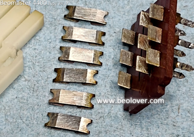
I used the Dremel and an ultrasonic cleaner to refurbish the damaged switch contacts. The results came out pretty good I think. I finished up the cleanup with a Deoxit treatment on the contacts and here is what they look like now.


Here are the cleaned up switch housings and actuators.


I have a decent selection of parts now to come up with a working Beomaster 4400 power on/off switch.

This set of components looks like my best bet.


The large switch housing piece has the hole in it from a burned contact but the rest of it looks pretty decent. After I re-install the contacts I can fill that hole with some epoxy.

For mating the two switch housing halves I can use a bead of hot glue again but I am thinking about drilling and tapping three M2 screw holes where the wide part of the housings (where the old mating tabs are). If I go that route I will use nylon M2 screws to join the parts.

Once I have the stationary switch contacts pressed back into the smaller housing I will solder on some connection wires to use when I place the switch back into the Beomaster.  I will make sure I protect the plastic switch housing when doing that soldering this time around.