Featured Post

Beolover SyncDrive: DC Platter Motor Replacement for Beogram 4002 and 4004 (Type 551x and 552x)

Late Beogram 4002 and the 4004 (Types 551x and 552x), which have DC platter motors instead of the earlier synchronous AC motors usually suff...

Showing posts with label 1934SLBG4002. Show all posts

Thursday, September 7, 2023

Beogram 4002 (5503): When Disaster Strikes! - Replacement of the Solenoid Switch and Restoration of a Melted Solenoid

Oh well! I recently received a Beogram 4002 (Type 5503) from a customer in Arizona with the indication that 'it does not lower the arm anymore'. I had restored the unit only in Dec. 2022, so this was a bit early for my taste to see it again!

After I removed the aluminum panels it became immediately clear why the arm would not lower again!:

The solenoid had completely melted down! I measured its resistance and it was about 1.2 Ohms. Normally it should have about 9 Ohms. Why this happened also became clear quickly. My solenoid arm extension part did not hold up. It cracked in a very similar way like the original arm extensions:
Because of this weakened arm link the solenoid switch did not get activated anymore and so the solenoid ran at full power even after the arm had been lowered. At some point the insulation of the coil wiring burned off, short circuiting the coil and that was the end of the arm lowering function. 
I extracted the solenoid
and took it apart:
Then I made a new coil. Luckily I recently learned how to do that:
This shows the new solenoid installed in the original bracket:
After I implanted the solenoid I had to realize that it would not activate at full power. This turned my attention to the solenoid switch. I found it to have a too high resistance when closed. And that caused the solenoid to be underpowered. Maybe the switch-terminals also suffered during the solenoid burnout. But it also did not click properly when activating it manually, so there was something wrong with its mechanics, too.
Since these switches are not made anymore, I had to figure out a 'modern replacement'. Immediately, I thought about the end switches used in 3D printers. They have a suitably small form factor, but they usually are only rated for switching DC currents up to an amp or so. Not enough for handling the typical 3-4 Amp current in the Beogram solenoid when it is activating. 
After a bit of thought I decided to try using a power transistor for the 'heavy lifting', and the switch only for activating the transistor. This approach promised reducing the mechanically switched current by about 2 magnitudes since the current gain of such transistors is typically in the 100x range. In other words the switched current promised to only be in the sub-100mA range. 
This is the simple circuit that I implemented using a end switch connected as a normally closed switch, so the TIP42 pnp transistor would be on when the solenoid is initially fired up to sink the solenoid directly into ground. This is the situation shown here (yellow beads show the main current flow):
You see that the simulation shows a voltage of about 0.7V at the emitter of the solenoid transistor. This means that the solenoid sees almost 40V driving it with about 4.3 amps based on its approximate 9 Ohms resistance.
After the solenoid activates and pushes its plunger out the solenoid switch gets hit and the TIP42 turns off, sending the current solely though the solenoid resistor. This causes the voltage across the solenoid to be dramatically lowered and with that the current gets reduced:
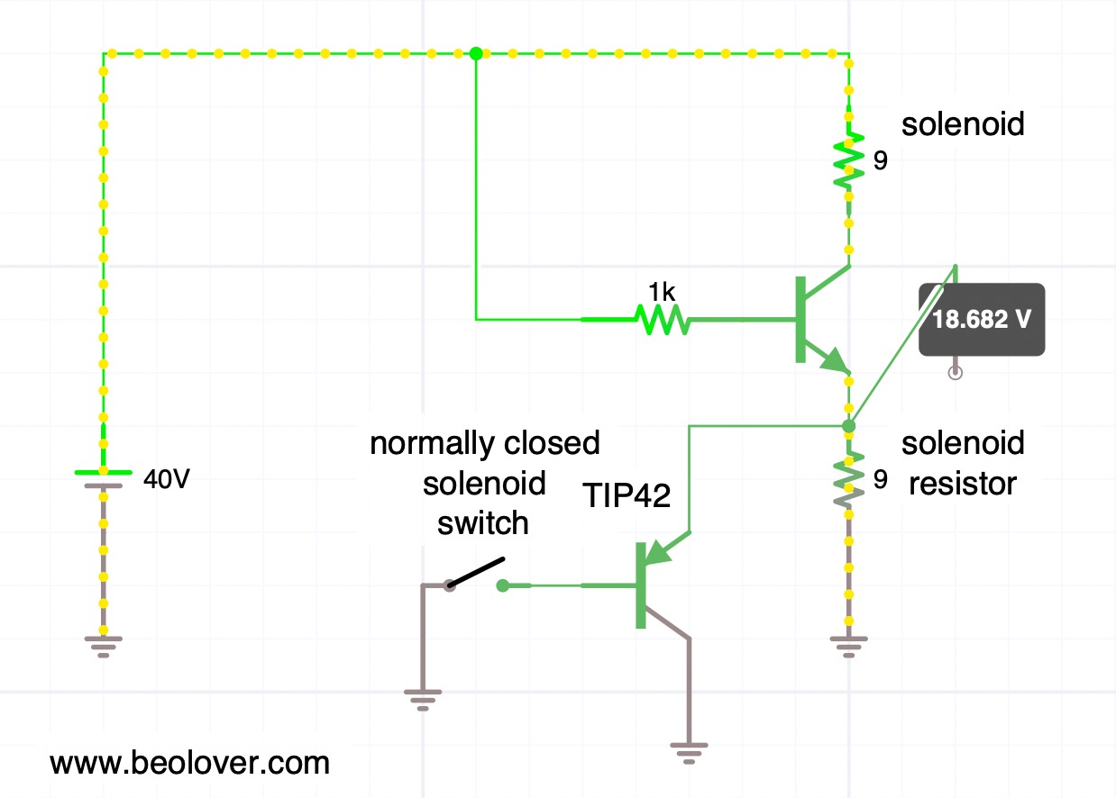
This situation is maintained during the play of a record when the arm is down.
This shows this concept put into practice on the solenoid switch PCB that I extracted to be able to work on it:
I found the best switch position by trial and error, and then drilled a hole into the circuit board so I could anchor it with a 2mm bolt in place. The TIP42C is bolted in via one of the two mounting screws of the PCB. The way it is connected still allows the board to be be shifted up and down to fine tune the switch position. This is important to make sure the arm hits the switch in a way that it really switches.
The last task was the re-design of my solenoid arm extension. I got rid of the nut and instead used a self-tapping 2mm screw that would put only minimal stress on the plastic. I added a liberal amount of epoxy in the bolt hole and the compartment that receives the end of the metal arm to keep things from separating. This shows the result:
Let's hope this holds up better!
Here you can see the arm in concert with the switch. First with the solenoid off:

And now with the solenoid activated:
Once the solenoid demonstrated to actuate properly, I measured the voltage across it during the activation process. In this measurement the trace corresponds to the signal measured at the collector of the solenoid transistor (0TR4).
But first I measured a reference signal that I was able to obtain conveniently from another 5503 that I have on the bench currently:
Before activation of the solenoid, the voltage at the collector is essentially the same as the power rail, i.e. ~40V. This means the solenoid has 0V across it. Once the solenoid transistor activates, the voltage across the solenoid increases to about 40V and then, after about 10ms, the solenoid arm hits the switch, and the solenoid gets disconnected from ground, and the current flows through the solenoid resistor instead. This results in a strong voltage reduction across the solenoid and it has now only about 8-10V applied to it. This real-life voltage is less compared to the simulation above. I think it comes from the fact that in the simulation I drive the solenoid transistor with an arbitrary 1k resistor connected to 40V, while in the real circuit a series of transistors (TR14/15/16) drives it with a different current.
What really counts is: Does the TIP42 replacement result in a similar behavior as with the original switch? Happily it does as is evident from this trace that I measured on the implemented circuit:
This trace is hardly distinguishable from the standard circuit behavior and so we can conclude that this may be a good fix for broken solenoid switches!
All good again in the arm lowering department of this Beogram 4002! Beolove is sometimes a bit painful, but only steady improvement leads to perfection. And that is what the Beolover aims to achieve!


Saturday, December 10, 2022

Beogram 4002 (5503): Complete Restoration

This post describes the work that was performed on a Beogram 4002 (Type 5503), that I recently received. The original condition of the unit as received is described in this post. A separate post describes the restoration of the carriage position sensor. It needed a replacement housing, which is described here.

This shows the unit with the aluminum panels removed:

It was in unadulterated original condition, the best starting point for a complete restoration. On the cosmetic end, the keypad had delaminated, and the keypad itself showed the usual finger smudges that are a result from acids and fats interacting with the clear coat that is on the pads to give them their nice slightly tan look to contrast with the aluminum surfaces. Luckily, one of us Beolovers has figured out how to restore these keypads to a like-new look, and this Beogram will get such a keypad installed!

As usual I started with rebuilding the carriage mechanics:
This shows the extracted parts:
A closer inspection of the solenoid lever revealed the usual crack through the rivet hole. Also as usual someone already glued it back together:
Of course the Beolover has a part for this!...;-):
This shows the repaired lever:
I cleaned the parts with an ultrasonic cleaner and also restored the brass surfaces to their original shine:
This shows the repaired solenoid lever installed:
There is one more linkage that needs to be extracted and re-lubricated. It is only accessible by taking out the sensor arm. This shows the arms assembly from the back:
I removed the sensor arm and extracted the damper-to-tonearm linkage:
As usual, the small copper pad that helps the tonearm sliding back into its parallel position when it is laterally moved while up, came off, too. It is only held in place by a small piece of double sided tape, which is often degraded at this point in time:
I cleaned the tape off and glued it back in place with a dab of epoxy:
then I replaced the cracked plastic carriage pulley
with a nice new machined aluminum pulley:
then it was time to replace the tracking sensor light bulb with an LED assembly. the original bulb is located in the black housing in this picture:
I removed the original housing. Here you can see it in comparison with the LED assembly:
This shows the LED light source installed:
The next step was to focus on the AC platter motor and the large electrolytic motor and reservoir capacitors:
I removed all components and opened up the motor:
Then I immersed the motor housing with its sleeve bearings in motor oil and pulled a vacuum to re-infuse the bearings with oil:
After 24 hours the bearings were ready and I put the motor back together. Then I installed new capacitors held in place with a 3D printed adapter:
Another light bulb to replace is found in the sensor arm where it helps detecting the presence of a record. This shows the small sensor compartment pulled out from the end of the sensor arm. The small bulb can be seen in the compartment. Next to it is the LED assembly:
While I installed the LED assembly, I realized that the photo cell had come loose. It sticks in the back of the compartment to measure the reflected light from the platter if there is no record:
If the cell is loose, it needs to be carefully extracted that contact cement can be re-applied to its back and the top of the sensor compartment. This shows the cell:
After the contact cement had dried, I re-installed the sensor and very carefully pushed it into its small notch at the top of the compartment:
This shows the LED board in action. A warm-white LED makes sure that there is enough red light to make the B&O logo light up properly:
Two more light bulbs for replacement are located in the RPM trimmer panel where they illuminate the RPM scales. This shows the RPM panel with installed LED boards:
When I tested the LEDs, I noticed that the 33 RPM scale had a wavy white background:
This happens due to the heat that comes from the incandescent bulbs. Usually, this issue is limited to the 33 RPM adjuster, since most Beograms are rarely used to play singles at 45 RPM, and so the white background tape remains flat behind the 45 RPM scale. This shows the wavy original background after I opened up the compartment:
I replaced the backgrounds on both sides with some cut to size 3M white electrical tape:
After re-assembly, the background looked smooth and homogeneous:
Beolovely!
After this I moved on to restore the carriage PCB, which serves mostly to detect the carriage position. The 'Plexiglas ruler' that is mounted to the carriage gets moved through a gap formed by a light bulb (right side) and a photo resistor (left side). This shows the detector with the carriage removed:
The photo resistor housing had lost its mounting tabs. This is an often encountered issue since the plastic appears to get brittle over the years.
In the past I glued the sensor to the PCB, but this time I decided to design a new part, so one does not have to mess with glue anymore. The installation process is described in this separate post. I also replaced the light bulb with an amber LED and a 3k resistor:
While I had the carriage up for the above repair I also replaced the solenoid transistor with a higher voltage rated C type. I already had to replace a few of them in the past, and so I made it part of the 'standard restoration process' as a preventative measure:
Now I focused on the main PCB, which is shown here in its original condition:
While it is lifted out, it is a convenient moment for replacing the transistors of the push-pull stage of the AC platter motor. This shows the new transistors installed:
On the main PCB I found a strange looking fuse F1. It was still intact, but had some depositit on the glass walls. This may have been the result of a near-blow where the filament reached a white glow and some metal got deposited on the glass:
This fuse is soldered into position, and so I needed to solder wires to the new replacement:
Then I replaced all the electrolytic capacitors, the power transistors and the RPM trimmers:
Next was the output PCB. This shows it in its original condition:
I replaced the muting relay and the electrolytic capacitor that gives the muting circuit its time constant. I also installed a (red) switch that allows connecting system and signal grounds in case there is a hum issue when connecting it to an amplifier:
As usual, I also replaced the main fuses in the small black fuse cabinet with new ones. They often have metal caps that have come loose from the glass bodies:
Then I adjusted the sensor transistor bias to get the prescribed 4V at the collector:
And then I tested the sensor response:
Then I adjusted the motor voltage and checked if the signal is a good sine wave:
If the waveform is distorted then either the voltage is too high, or there is an issue in the Wien oscillator circuit.
Since I worked on the carriage sensor, I also measured the sensor response: this shows the signal while the 45 RPM switch pattern moved though the sensor:
All good in the sensor department!
The next step was to qualify the platter drive with the BeoloverRPM device, which allows logging the RPM over longer periods of time:

This is the curve I measured over 24 hrs:

This is as good as it gets. But not surprising. So far I did not encounter an AC Type Beogram 4002 that had RPM instabilities.

On to replacing the cracked plinth guidance washers
and the deteriorated transport lock bushings.
My replacement parts are 3D printed from nylon, which promises they might last for a while.
Now it was time to do the adjustments. First I leveled the floating chassis and made sure that the platter and arms are in their proper positions relative to the aluminum panels. Once all that was in place, I adjusted the arm lowering limit
and calibrated the tracking weight:
Finally, I adjusted the tracking feedback:
Then it was almost time for a first test run, but I still needed to replace the corroded DIN5 plug with a nice gold plated all-metal plug:
Finally, after a deep clean of the aluminum plates and the installation of a rebuilt keypad, the moment had arrived to put a record on the platter! I selected one of my favorite George Benson records, his 1976 album "Good King Bad" (CTI 6062). Of course, this album had been thoroughly ultrasonically cleaned on a CleanerVinyl ProXL setup combined with a multi-frequency cleaner before play. Beautiful!:
I will now play this lovely Beogram 4002 a bit more to make sure it does not have intermittent issues and is stable. And then it will be time to send it to its new owner!