Featured Post

Beolover SyncDrive: DC Platter Motor Replacement for Beogram 4002 and 4004 (Type 551x and 552x)

Late Beogram 4002 and the 4004 (Types 551x and 552x), which have DC platter motors instead of the earlier synchronous AC motors usually suff...

Friday, January 24, 2025

Beogram 4000: Installation of a New Reed Relay

This is the third installment of my 'this Beogram keeps on giving' series about the Beogram 4000 from Australia that I have on my bench currently (in other words the Beolover is having some fun!..;-):

After fixing the tonearm wiring and the broken photocell in the sensor arm, this Beogram decided to give me a never experienced before new phenomenon:

After pressing OFF, the carriage returned home as it should, but after touching base, it decided to go back for an inch or so until it decided to finally come to rest. As if someone pressed ON again and then after a few milliseconds one of the < or > keys to bring the carriage to a premature stop before setting down on the record. Very strange! This was completely reproducible, i.e. happened every time I tried. Otherwise the deck seemed to perform normally.

After a bit of head scratching it occurred to me that maybe the 24V rail that controls the analog part of the control system did not shut down properly after the carriage triggered the off switch. I examined the reed relays that control the power in the Beogram 4000 and it became quickly clear that the one responsible for this 24V rail was stuck on closed.

The power supply setup in the Beogram 4000 can be a bit confusing, so a while ago I already made a schematic labeling some of the 'ingredients':

There are four reed relays (i.e. relays that are activated by a magnetic field generated by a surrounding coil to ensure galvanic separation of the circuits) that are controlled by two coils. These coils are the two big yellow items in the picture above. Each coil has two round passages into which the glass relay tubes are inserted. On either side the relays are connected with solder tabs that are inserted into the circuit board below and soldered to it on the backside. 
The upper coil relays control the 24V platter motor power and the power to the strobe light. Since the strobe light runs on about 90V that come from a dedicated secondary winding in the transformer this relay is fully insulated with shrink tubing.
The lower coil contains the 6V relay that controls the power to the digital control system inside the keypad cluster (basically the 'brain' of the 4000...;-), and the 24V relay that supplies power to the analog part of the control system (the 'muscle'...;-). 
This latter 24V relay is the one that was the root cause for the observed phenomenon. This was quickly confirmed with a multimeter, showing continuity across it even when the power plug was pulled.
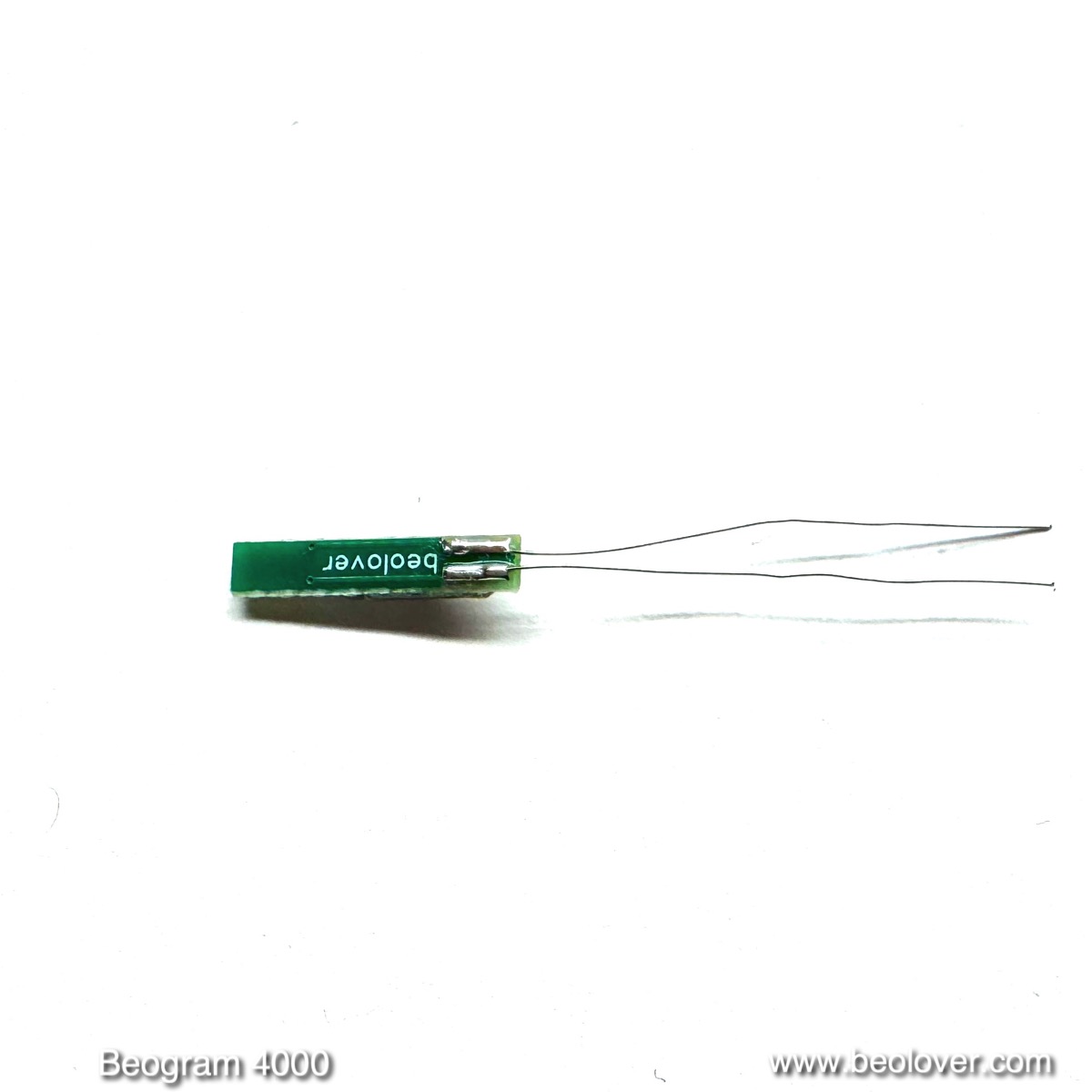
Luckily there are replacements available. This shows a new Beolover Reed relay for Beogram 4000 Power Supply:
The relay exchange is slightly messy. This shows the original setup with the 24V relay still in place:

For removal of an old relay, it seems best to remove its solder tab on the left side first and then unsolder the other end of the relay from the solder tab on the right. This makes it easy to pull the relay out towards the left which is less obstructed. Be careful to not damage the very fine magnet wire that connects to the coils when you try this at home.
The first step is to remove the solder at the point where the relay connects to the tab with a solder sucker. Then the tab can be bend a bit away from the relay pin and then from the backside of the board the tab can be unsoldered and removed. The next step is to unsolder the other end of the relay and then it can be pulled out. Note that it is easy to damage the wire insulation of the red wires that are also attached to this tab. This shows the setup after removal of the relay tube:
Here a picture of the extracted original relay (top) together with the new one:
The new ones are slightly shorter but have longer pins. This makes installation relatively simple. The first step is to cut the right side pin to the proper length and then insert the relay followed by soldering it to the right tab. Then the left solder tab can be slid over the relay pin and pushed back into the PCB followed by soldering in place. The final step is soldering the relay pin to the tab and cutting the excess of the pin off. This shows the final result of the implantation:
After this procedure the Beogram performed again normally. On to finishing this project up!

Beogram 4000: Installation of Beolover RIAA Pre-Amplifier

I am making good progress with the restoration of the Beogram 4000 from Australia that is currently on my bench. This post reports on the installation of the Beolover internal RIAA pre-amplifier for Beogram 4000 in this unit. This shows the board before installation:

The red wire is for making the connection to the 24V power rail.
For more information about the performance and measurement data on the Beolover RIAA circuit, please, visit this post. The Beogram 4000 RIAA uses the exact same circuit like the discussed Beogram 4002/4004 version in the above post.

This shows the original setup around the output terminal where the DIN5 cable connects to the tonearm wiring:

The installation of the Beolover RIAA for Beogram 4000 is pretty straight forward. Just unsolder the output cable and use a solder sucker to clean the terminals:
The RIAA board bolts directly ontop of the original output terminal using its screws:
Use the elongated mounting holes to push the RIAA board input pads as far as possible towards the terminals:
If necessary bend the terminals to be close to the pads. Then solder the terminals directly to the input pads using a generous amount of solder:
The next step is to feed the red power wire along the keypad cluster, underneath the strobe light assembly and then up to the main PCB next to the red wire that is already soldered to its solder side:
Then connect the RIAA red power wire to the same terminal where the other red wire is already connected:
This connects the RIAA board to 24V.
Then the output cable can be reconnected to the RIAA board output pads. They are spaced exactly like the solder fins on the original output terminal, i.e. the wiring setup does not need to be changed at all:
This shows the entire board as installed:
The final step is to pull the output cable a bit out of the enclosure to compensate for the depth of the RIAA board. For this the cable retainer at the feedthrough needs to be unbolted:
After pulling a couple inches of the cable though the opening, the retainer is bolted back into place to secure the cable in its new position:
And this concluded the installation. On to some final adjustments and a first test spin with this lovely Beogram 4000!

Thursday, January 23, 2025

New Beolover Carriage Position PCB for DC-Motor Beogram 4002/4004s (Types 551x and 552x)

I always found the repair and adjustment of the carriage position sensor on the PCB underneath the carriage somewhat tedious. The board and circuit are designed in a way that make a precise alignment of the LED, sensor and plexiglass ruler across the entire travel of the carriage necessary to ensure proper functioning. At the same time photosensor failures and mechanical failures of the sensor housing or the two switches on this board were sometimes difficult to fix, while broken off wires occasionally caused operational issues.

So I decided designing an improved board that would provide a reliable fix for all these issues at least in DC-motor Beogram 4002/4004s (Types 551x and 552x), where this board can be easily replaced. This shows the final design of the board:

The board features new SO and ES switches, as well as a modern monolithic IR photo-interrupter whose signal is cleaned up and shaped by an opamp in combination with a Schmitt trigger. It connects with a modern harness using a 2.54mm 8pin adapter to match the classic Molex jack on the main PCB. This connection should last much better than the original soldered wires.

The part is now available at the Beolover Store. I also gave this board a built in sensor test feature. Flip the switch to the right and an integrated LED will light up every time a black band on the ruler is properly identified by the sensor:

This shows the board installed:

My tests yielded a proper carriage position detection, while the SO and ES switch were in the correct location and performed perfectly. It seems that the modern photo interrupter due to its fixed alignment between LED and phototransistor is much more forgiving regarding the distance between ruler and photosensor. This makes the alignment between ruler and sensor across the entire translation range of the carriage much easier.
A good test for the proper functioning of the position sensor is whether it can read out the run out groove detection pattern at the end of the ruler. I measured the signal at the collector of TR17 while this section passed through the sensor:
A nice clean trace! All good in the carriage position detection department!


Wednesday, January 22, 2025

Beogram 4000: Installation of New Beolover Sensor Arm Photocell

The Beogram 4000 from Australia that I am restoring right now kept on giving! After I fixed the tonearm wiring to get both stereo channels working further tests revealed that it would not recognize the absence of a record and eagerly put down the arm onto an empty platter. Luckily I had already adjusted the arm lowering limit and so nothing happened to my MMC20 EN cartridge.

Ignoring the absence of a record is a telltale sign for a dead photocell in the sensor arm. The circuitry recognizes a dead sensor arm bulb and shuts down arm lowering if this is detected. However, a damaged photocell is not recognized. It simply simulates a black surface on the platter, and so the arm lowers.

I pulled out the sensor compartment and closer inspection revealed that one of the two electrodes on the photocell had disconnected. It looked like this:

This photo is from an earlier post about this type of issue, where the photocell of a Beogram 4002 had come apart. This earlier post reports about my initial development efforts aiming for a suitable replacement of the original photocell. 
I removed the photocell fragments:
And then it was time to install the newly designed Beolover Sensor Arm Photocell for Beogram 4000, 4002, and 4004. It is available via the Beolover Store. This shows the business side of the part:
At the front end (left) there are three photodiodes in parallel (to ensure sufficient current generation). On the back end (right) a 3D printed alignment piece is installed that helps keeping the cell properly oriented and in its proper spot relative to the lens in the sensor arm compartment.
This shows the backside with the two contact leads:
This is a real photocell like the original. It puts out ~0.45V photovoltage when exposed to sufficient light:

This means that unlike with other photocell replacement schemes no circuit modification is necessary. This is a direct drop-in part that replaces the original photocell (B&O part 8760002)
Installation is simple: Just stick the leads into the holes in the small circuit board attached to the sensor arm compartment (it is a good idea to use a solder sucker to remove the solder from the solder pads on the backside of this board to ensure the holes are open after unsoldering the original cell):
Then insert the photocell into the small compartment where the original cell was located and align the small protrusion on the alignment piece with the hollow rivet that holds the PCB to the plastic part: 
Then press the back end down until the frontend with the photocells hits the roof of the compartment:
Then the leads can be soldered to the pads on the underside of the PCB:
This shows the underside with the red and blue photo cell leads attached:
I tested the new cell with my oscilloscope, which was connected to the collector of the sensor transistor 1TR14 whose collector DC bias was adjusted to be 1.8V:
 
The photocell yielded a strong 2.5V amplitude signal over the rotating platter. More than spec. So all is good again in the record detection department.


Thursday, January 16, 2025

Beogram 4000: Microsurgery on the Tonearm Wiring

In recent days I made nice progress with the Beogram 4000 from Australia that I have on the bench right now. When I thought I was mostly done I wanted to give it a quick spin to see if any sound would come out of the unit. Unfortunately, I quickly noticed that only one of the channels would produce sound. The other was completely dead.

First I did some measurements between DIN5 pins and cartridge mount connection pads (after preventing the grounding switches from closing with a strip of paper). This yielded that indeed the red (right) channel did not seem to be connected. But I also noticed that blue/green (the signal return wiring) seemed to connect to the center tabs and not the outer ones on the cartridge mount, as would be normal. This suggested that some major 'human creativity' had occurred at some point in the past that changed the tonearm wiring fundamentally. Probably in an attempt to fix this issue.

I did a visual inspection of the wiring, and soon found the root cause for the absent continuity of the right channel: One of the very fine wires that go though the bearing of the tonearm assembly was broken off:

If you look very closely you can actually see the other end of the wire peeking though the thin plastic tube a couple mm from the end of the tube. This meant I needed to find a way to restore the wiring. Luckily, this very thin wiring stretch terminates at the bottom end of the bearing where the wires connect to more solid wires across a small PCB acting as a wire terminal:

I decided to try reconnecting the two wire ends. For this to happen I needed to get the ripped off end inside the tube out in the open, so I could solder the two ends back together. I unsoldered the wires from the terminal PCB and then liberated the plastic tube from the clamp that secures it to the bottom of the carriage assembly:
It turned out that the wires sit fairly loosely inside this tube and I was able to push the broken off wire a bit further into the tube, which happily caused the broken off end to emerge. With fine tweezers I pulled the strand a bit further into the open. These wires are so called 'magnet wire', which means they are insulated by a thin coat of polyurethane. This coat can be burned off in a drop of hot solder at the end of the solder iron tip. A puff of smoke and one has uninsulated wire that can then be soldered. I did this to both ends and then tacked them back together after applying a little bit of flux: 
I then insulated the naked wire stretch with some glue:
I verified that this wire was continuous again and then proceeded identifying which of the wires was connected to what wiring color on the MMC mount. This shows how the colors are connected to the Beolover MMC cartridge mounting tab that I had already installed in this Beogram:
One by one I measured where the thin wires were connected at the tab and then I soldered them to the proper terminal to match the colored wiring on the other side:
This shows the final result on the other end. I had pulled the plastic tube out a bit further than before to give the wires some clearance to the metal bearing shaft, hoping to prevent future damage to them due to reduced stress and no mechanical contact:
I installed the carriage back on its rails and then tried listening to a record again. Happily, the music now came from both speakers, so we can conclude that this issue is fixed. Stay tuned for more details about this restoration effort!


Saturday, January 4, 2025

Beogram 4000: A New Arrival From Australia - First Look

This post gives a first assessment of a Beogram 4000 that I received a few months ago from a customer in Australia for a full restoration.

The unit came very well packaged in a foam padded double box, so there were no shipping damages. I extracted the unit and put it on the bench:

It has very nice aluminum surfaces. The platter is almost without nicks and there is only a small ding in the platter surround, probably from transporting the unit without tightening the transport locks at some point:
The only real blemish is the damaged left front corner of the wood plinth:
Luckily there are now very nice replacement frames available from Christian Hakansson. They are CNC machined from solid wood and look just stunning! 
The other corner is still in good shape:
The hood hinge has the often seen corrosion:
This can usually be cured by sanding and re-coating.
I removed the panels and the platter and had a look 'below deck':
After this visual inspection I installed a new carriage pulley (the original one had come off) and belt, and plugged the unit in and pressed ON. The carriage started moving and found the LP setdown point, but the solenoid did not activate. Also the platter motor did not run. It only did a little twitch. Nothing out of the ordinary, really. These units often have issues with their power transistors.
Also noticed a very harsh almost bluish back light (my camera did emphasize the blue shade, to me it looked just like a cold white) of the arm position indicator:
Furthermore, the 33 and 45 trimmer backlights seem out of order.
So, while the unit overall looks pretty original, there was definitely some previous 'human creativity' involved. I am curious about what I will find in this keypad cluster!...;-).
Overall, I think this Beogram 4000 is an excellent starting point for a successful restoration. Stay tuned for the restoration report!