This post describes the complete functional restoration of a Beogram 4002 (5513) that I recently received from a customer in Tennessee. The post about my initial evaluation of this unit can be found here.
This shows the unit in 'service position' with the platter and aluminum panels removed:
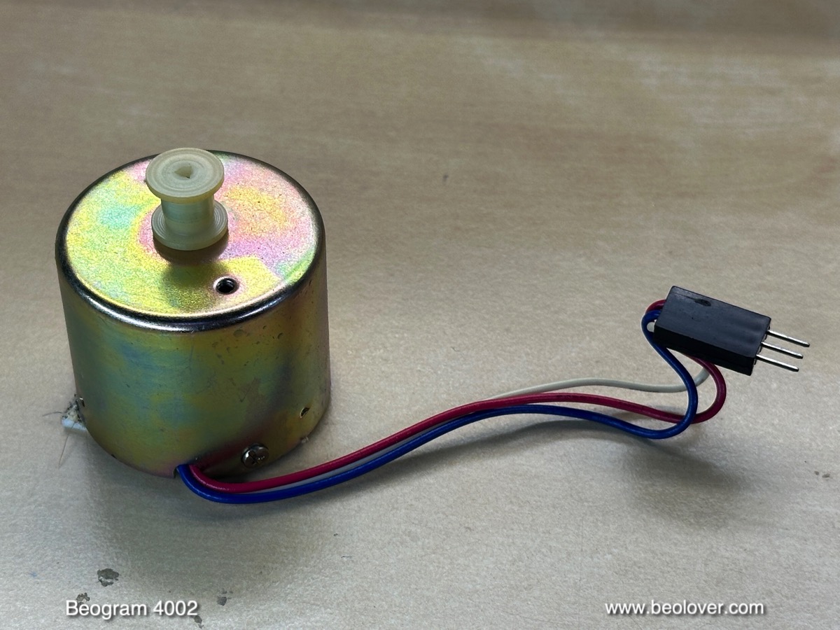
Pretty much all DC-motor Beogram 4002s need the bearings in their platter motors re-infused with oil. Over time the oil stored in the bearings gets depleted while playing records. This causes dry bearings and many Beograms end up with RPM stability issues. The oil infusion usually takes a few days and so I usually start with extracting the bearings from the DC platter motor. This shows the extracted motor:
I disassembled it to get the bearings out. They are the two small donuts on the black pad up front:
I immersed them in motor oil and pulled a vacuum. Immediately, vigorous bubbling started:
The bubbling represents air drawn from the empty pores of the Oilite bearing material. This makes room for oil to diffuse into the bearing. The process is complete when the bubbling stops. This usually happens after 2-3 days.
While this process went on, I focused on the remaining restoration tasks. As usual, I restored the carriage first. The carriage harbors the arm lowering mechanism, which is often motion-impaired due to hardened lubricants. This shows the relevant sections comprised of solenoid and damper plus connecting linkages and springs:
I removed all the essential parts,
as well as the spindle that moves the carriage and the rods it travels on. This shows the removed parts ready for ultrasonic cleaning:
I usually run the cleaner for 1-2 hours to get everything nice and lubricant-free:
Then it was time to reassemble everything. First, I put a new gasket into the damper:
This is an essential step in the restoration since it ensures a reliable and consistent arm lowering experience. The original rubber rings are often hardened and this cause problems when they seat against the plunger. This can cause sudden arm drops instead of a controlled smooth lowering.
This shows the reassembled mechanism:
I also replaced the already cracking carriage pulley
with a precision machined aluminum replacement:
There is one more linkage in the arm lowering mechanism that needs attention: It connects the end of the damper with the actual arm assembly. This linkage pivots on a small shaft that is mounted on the sensor arm assembly.
The linkage is located between the two arms and can be seen poking out from the back of the arms assemblies. It sticks out from the V cut on the part that is bolted to the back of the counter weight:
For the re-lubrication of this pivot point the sensor arm needs to be removed. This shows it with the linkage already removed (watch out for the small spring that is under the retaining clip if you try this at home):
Of course the small copper sheet under the arm lowering limit adjustment screw also came off:
It is originally attached with double sided tape. I usually clean the tape residue off and then epoxy it back into place.
After re-installing the sensor arm it was time to focus on rebuilding the electronics. I started out with the main PCB. It has two power transistors mounted on the solder side, i.e. they are accessible from the top while the board is still bolted in place. It is good practice to start with replacing them first since they need to be bolted to the PCB in the correct location to match up with the PCB mounting holes (essentially, the design uses the mounting posts on the enclosure as heat sinks for the transistors).
This shows IC1 as an example. It is originally a TIP120 npn Darlington:
I usually replace it with a stronger TIP102 for longevity:
For some reason the installation of modern TIP devices causes unwanted oscillations on the 21V power rail, which can throw off the record detection circuit. This issue can be squashed by installing a 100nF capacitor on the output of the TIP (yellow device in the picture above).
After replacing the other power transistor I removed the board to get to the components on the other side:
This shows a close-up of the RPM control section of the circuit, composed of RPM relay and RPM trimmers:
I replaced all electrolytic capacitors, all power transistors, the high-gain transistor of the record sensor circuit and the RPM components:
This shows the rebuilt RPM section with the new relay and modern 25-turn trimmers enabling a more accurate RPM adjustment:
The next step was replacing the four incandescent light bulbs that are used for various functions of the Beogram with LED assemblies. LEDs promise to live much longer than incandescent bulbs.
First I replaced the bulb in the tracking sensor. This shows the original setup:
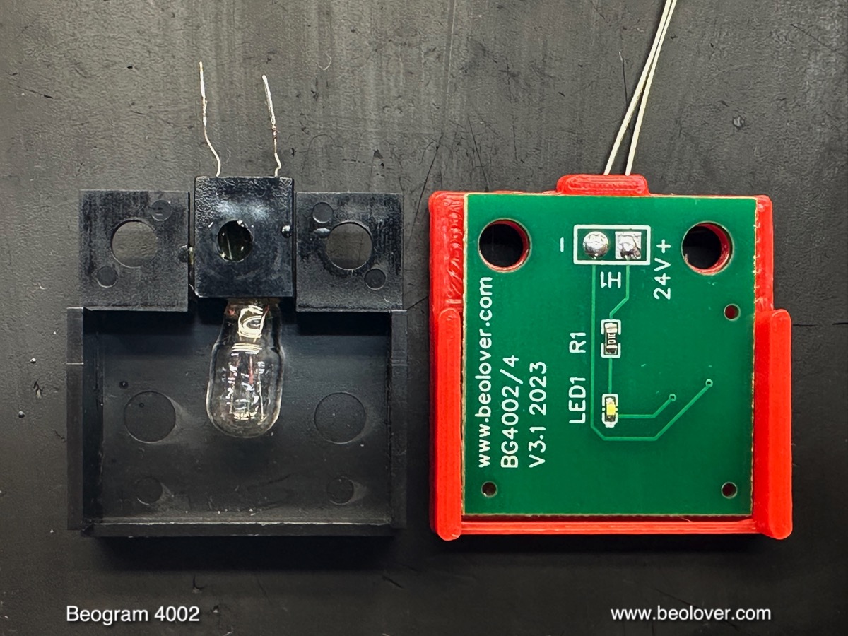
I removed the original bulb housing. This shows it in direct comparison to the Beolover LED replacement assembly:
A small SMD LED is doing the job of the bulb. It is located approximately at the location of the bulb filament. I installed the LED part:
The small white box on top is a trimmer that allows adjusting the light intensity of the LED. This can come in handy when adjusting the tracking feedback. Next came the light bulb in the sensor arm. This shows the small compartment at the end of the arm pulled out with the bulb still installed:
Next to the compartment is the Beolover LED replacement together with its alignment aid.
This shows the small board installed with the extracted bulb:
The final two bulbs are located in the RPM adjustment panel. This shows the panel taken out:
I removed the bulb covers. This shows the bulbs still in place together with the Beolover LED replacements:
The LED assemblies solder directly to the solder points of the bulb:
This shows one of them in detail:
The small boards essentially form an extension of the PCB that holds the bulbs. After installation the bulb covers can be re-installed without interference:
When I extracted the RPM panel from the keypad cluster, I found cracked RPM panel holders on both sides:
This seems to happen fairly often, possibly due to misalignment during RPM panel manipulation. Luckily, there are now
reproduction parts available from the Beoparts-store in Denmark. All one has to do is extracting the springs from the old cracked parts and transfer them to the new ones. This shows one of the new ones installed:
With the keypad out, the output board could be extracted:
It does not have many components in the 4002:
I replaced the output relay and the electrolytic capacitor that defines the arm lowering time constant. I also installed a (red) switch that allows connecting system and signal grounds in case there is a hum issue:
Then it was time to remove the floating chassis for cleaning out any debris from the degrading transport lock bushings:
This is a common issue with the 4002 and these bushings need to be replaced. This shows the emptied out enclosure:
After vacuuming it out it was time to install the new bushings and then put the deck back together. The Beolover replacement bushings are designed for easy installation. They consist of two equal parts that simply insert from top and bottom into the orifices on the floating chassis:
This shows one of the bushings installed:
At this point I also replaced the original reservoir capacitor. This Beogram 4002 came 'ready for installation of a CD-4 output board', i.e. has a dual capacitance reservoir capacitor. It essentially contains two capacitors (1000 uF and 4700 uF) with a common ground connector:
The other end of the can has two contacts, one per capacitor:
Such capacitors are not manufactured anymore and so I designed an assembly composed of the two modern capacitors and a 3D printed holder that fits into the mounting clamp of the original setup:
Once everything was together again, it was time to tie up some loose ends. First came the adjustment of the sensor arm transistor bias to yield 4V at the collector. I usually do this with the trimmer temporarily installed on the solder side of the board so it is accessible while the deck is powered up:
Once it has been set, I remove it and install it in the location of the original fixed 1MOhm transistor on the component side. Here you can see it with the new BC549C high-gain sensor transistor (the original ones are often out of spec and do not have enough gain anymore for reliable record detection):
Then it was time to check the sensor response with an oscilloscope. This shows the sensor response I measured at the collector of TR3 with the platter manually rotated:
The signal looks perfect and its amplitude exceeds the 5V spec in the manual, i.e. everything is beolovely now in the sensor department! Here a couple pictures of the visible LEDs in action. This is the sensor arm:
Since I use a warm-white LED it has enough red photons to properly illuminate the B&O logo. This is a picture of the 33 RPM trimmer illuminated by LEDs:
Also a very nice natural incandescent look.
At this point the motor bearings had finished their infusion. I extracted them from the oil
and re-assembled the motor. I installed it in the Beogram and adjusted the RPM trimmers on the PCB to get the proper 33.33 and 45 RPMs:
Next I used the BeoloverRPM device for measuring an RPM stability curve over 24 hrs. The BeoloverRPM can log the RPM in 10s intervals for extended periods of time, perfect for detecting intermittent RPM issues. This is the curve I measured:
This looks pretty good for a DC-motor Beogram. The small variations are a result of the analog control system, which is susceptible to temperature variations and the moon phase (joke alert!...;-).
This restoration was coming to a close, and it was time to focus on the adjustments. First came the adjustment of platter height and parallelism relative to the arms, then the adjustment of the floating chassis to make the platter flush with the surrounding aluminum panels while ensuring proper ranges of motion in the three open transport locks. After this process I focused on the calibration of the tracking weight. My first step is usually replacing the flimsy original circlip that holds the adjustment screw of the counter lock in place
with a M3 nut:
This nut allows locking the counterweight position reliably in place, which enables the Beogram to be shipped without the need for re-calibrating the tracking weight after arrival at the customer site.
Then I calibrated the weight adjustment wheel to be accurate around 1.2g, which is the usual weight for B&O cartridges:
The next step was adjusting the arm lowering limit to miss the lower parts of the platter ribs by about 1mm:

This is an important adjustment since it is a fail-safe should the circuitry ever decide to let the arm to lower on an empty spinning platter due to a circuit malfunction.
The final adjustment was the tracking feedback to ensure a smooth and precise advancement of the carriage during record play:
My customer decided letting me install the
Beolover Commander remote control in his Beogram. Since it still has a pretty nice keypad, I advised getting the remote control. It allows controlling all functions of the Beogram with an Apple remote so the keypad does not have to be used anymore. This preserves it in its current state.
The Commander is easily installed in DC-motor Beograms by simply plugging it into the keypad connector, and then putting the keypad plug into the receptacle of the Commander board. The auto-repeat indicator of the Commander installs under the RPM panel. It uses the CD-4 indicator on the RPM panel to signal auto-repeat activation. This shows the commander installed:
A view with the RPM panel installed again:
The last step of this restoration was replacing the glued on rubber bumpers that 'replaced' two missing original ones:
I had a couple original bumpers in my 'stash', which made it simple:
And now it was finally time to give this completely restored Beogram a first spin!
I selected one of my favorite George Duke albums, "Liberated Fantasies" from 1976. It was produced by
MPS Records, that made quite a few interesting jazz records in the Black Forest in the 1960s, 70s and 80s. They started recently releasing some of their iconic records on vinyl again. My Liberated Fantasies copy seems to be a 1977 reissue on the Delta Label in the Netherlands (5C-064D-99392).
Of course this lovely vintage album was cleaned ultrasonically with a
CleanerVinyl ProXL setup to restore its original sound. What a lovely combination!:
I will now play this Beogram 4002 for a while to make sure it does not have any intermittent issues. And then it will be time to send it back to its owner in Tennessee!