Featured Post

Beolover SyncDrive: DC Platter Motor Replacement for Beogram 4002 and 4004 (Type 551x and 552x)

Late Beogram 4002 and the 4004 (Types 551x and 552x), which have DC platter motors instead of the earlier synchronous AC motors usually suff...

Wednesday, August 23, 2023

Beomaster 1900 Type 2904: Reassembly and Testing

Continuing from the last post, I performed two of the Beomaster 1900 Service Manual adjustments.
The No-load Current Test (12mVdc across the output amplifier emitter resistors).


...and the P1 and P5 Tuning Voltage adjustments.


The Beomaster was now ready for reassembly and some audio testing.

The first step was to re-install the plastic masks for the Bass, Treble and Balance controls.


After that, the button panel is installed.


The button panel installation is a little tricky. There are 10 touch control buttons.  Each button has a metal spring connecting the panel button to a corresponding metal post soldered onto the main board.
When installing the button panel you have to make sure all of the button springs mate with their metal circuit board posts.  

My technique is to get most of the spring contacts to mate...8 or 9 out of 10 is good.

For the spring contacts that do not successfully mate, they can be corrected using a prong tool from underneath frame.

Here is an example of one of the springs not mating.


The picture on the right shows the corrected spring contact mated with the post.

I screwed down the button panel and powered the Beomaster 1900 on to check if, indeed, all ten buttons worked.

They do.


Now for the installation of the program panel and test play some music through the Tape input.


I used both speaker outputs of the Beomaster 1900 during this initial audio testing.
A pair of Beovox MC120.2 speakers on Speaker 1 and a pair of Beovox S-55 speakers on Speaker 2.

They sounded very good so I finished up the re-installation, installing the bottom cabinet plate.

I hooked up an FM antenna and did some listening tests on the tuner.  P1 through P5 all tuned successfully and also sound very good.


While a successful listening test carries a lot of weight in judging the success of a restoration, I like to do a basic harmonic distortion test at full power and a 1000 Hz sine wave input (on the Tape input).
I also like performing a 20 Hz to 20KHz frequency response test at full power (again, using the Tape input as the source).

For these audio measurements I use a QuantAsylum QA401 Audio Analyzer.  There is a newer QA403 available now but the QA401 is still very good and I continue to use it.


I always mention that my audio tests cannot be directly correlated with what is printed in the service manual (or B&O published specs) as the equipment in the mid-seventies was quite a bit different.
Also, many of the specs are a little vague regarding how, specifically, they were performed.

For that reason, I try to do my tests the same way each time using my audio analyzer, then compare my results to previous results I measured on other restoration projects.

My speaker loads for the audio tests are fixed resistors that provide an 8.08 ohm speaker load for each channel (Left and Right).

8.08 ohms because each 8 ohm load resistor assembly is made up of one 4 ohm load in series with a 0.08 ohm, sense load and two 2 ohm loads.


The reason for that is because the QA401 audio analyzer has a limit of 28 Vp-p (or 19.8 Vrms).
19.8 Vrms = 26 dBV which is the form of the input value QuantAsylum uses in stating the amount of input.

At full power of 20W output across 8 ohms, the Beomaster 1900 maximum output my QA401 should see (across the dummy load resistor assembly) is 22 dBV.  So I can place my QA401 differential measurement probes across the full 8.1 ohm dummy load safely.

If I really want to be at a safe measurement difference I could put my QA401 probes across one of the other sections of the dummy load (i.e. across the 4 ohm resistor, the 2 ohm resistor or the 0.08 ohm resistor).  However, the best results should come from using the highest output level I can safely use.

Here are my distortion measurements at maximum rated output power (or as close as I could get) across the 8.1 ohm dummy load. (The Tape input source was a 1KHz sine wave at -12dBV).  

Left THD: 0.038%
Right THD: 0.062%


The volume control for this Beomaster 1900 version is only adjustable in sixteen steps.  Later serial number units (serial number 1826011 and on) increased the volume selection steps to 128.  The output power is the same power but the volume adjustment is much finer.

Because of the coarser, sixteen step volume control, I played around with the volume control value and my source sine wave generator amplitude to achieve an output that was close to the maximum rated power for this amplifier. 

I am pleased with the harmonic distortion measurement results.  Although, as you can see, the Left channel is producing 20% more power than the Right channel.

I measured the audio test signal through the Beomaster 1900 pre-amplifier to its voltage amplifier stage in the output amplifier.

At the input to the output amplifier (Test Points TP201 and TP302 for the Left and Right channels respectively), the Right channel is about 10% lower than the Left channel.
When the signal is at the collector of transistors TR212 (Left channel) and TR312 (Right channel), the difference in the channels is 12%.


I will do some more investigating on the difference in output level between the Left and Right channels.
It appears that most of the difference occurs in the output amplifier.

Meanwhile, I continued on to a frequency response measurement at maximum power. 
I ended up with a little more volume for the measurement and the Left channel output was 5 Watts over its rated value.
The measurements are within the expected value for this amplifier but again, the Left channel output is higher than the Right channel (by 23%).




Friday, August 11, 2023

Beomaster 1900 Type 2904: Post Recapping Power On Test

Power can now be applied to this Beomaster 1900 unit.

Standby mode works


...and the On mode (when a source is selected) works


Here is how I arrived at this point since the last post.

I performed one key service manual voltage adjustment, 15-Volt Supply.


I performed the capacitor replacements on the Control Panel PCB.
Here are the before photos of the Control Panel recapping.


In addition to the capacitor replacement I opened the three slider controls (Bass, Treble and Balance) to inspect and clean them.

The Balance control was in great shape so it only required cleaning.


The Treble control had a broken plastic slider bridge.  It is the typical problem where the plastic piece holding the contacts in place gave way.


This is very common and the Beoparts Store carries a replacement slider bridge for this problem.


Continuing on, the Bass slide control was in great shape like the Balance slider was...so it only required cleaning.


Here is the Control Panel PCB recapped and ready for use again.


After the Control Panel tasks were done I replaced the lamps in the lamp modules.

I replaced the incandescent lamps with new incandescent lamps from Beoparts on the Volume indicator and Source Select boards as the lamps themselves make up the functionality of their respective circuits.


On the lamp panel for illuminating the slide control indicator masks, I like to change to LED lamps.
The reason for that is because the LEDs produce less heat under the plastic lenses and indicator masks.
These lamps are always on when the Beomaster is not in Standby mode and are powered by the 15 V power supply. They aren't part of any audio circuit functionality like the other lamps in the Beomaster are.


In the next post I will do some more voltage checks and will adjust the No-Signal (idle) current of the output amplifier along with a few other service manual checks. I will also connect up some Beovox speakers and see how this amplifier sounds.

Saturday, August 5, 2023

Beogram 4002 (Type 5513): A New Arrival from California - First Assessment

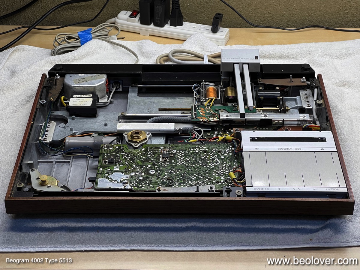
I recently received a Beogram 4002 (Type 5513) from a customer in California. It traveled in a Beolover provided shipping container and so everything went well with the shipping process. This post discusses my first assessment of the unit. This is the unit as extracted from the box:

The deck is in decent cosmetic condition, but it has the usual finger marks on the keypad:
There are also a few minor scratches in the main aluminum panel:
The plinth corners are fairly pristine on the other hand:
The hood broke loose from the hinge at the bolts:
Unfortunately, this is a common occurrence caused by stress from the flat head bolts sunk into the plexiglass. This results in lateral stress, which over the years causes cracking of the plastic. Luckily, new hoods are now available from the beoparts-store in Denmark.

After I removed the aluminum panels
I found a fairly original setup without major evidence of previous human interaction. But I found a bunch of fragments from crumbling transport lock bushings next to the DC platter motor:
This was confirmed by the complete absence of said bushings from the locks:
The plinth guidance washers had already been replaced with regular washers:
This is less than ideal since normal washers do not guide the plinth.

After this visual inspection I plugged the deck in and pressed start. The carriage started moving and the platter motor came alive with a rumbling noise, indicative of dry bearings. This is almost a to be expected issue with these decks as the motor bearings usually ran dry after many years of usage. On the positive side the arm stopped at the LP setdown point, indicative of a working carriage position detection system.
In summary, I think this will be a straight forward functional restoration. Stay tuned!


Friday, August 4, 2023

Beogram 4002 (5503): Repair of a Dead H-Bridge and Some Other Updates

Sadly, an AC-motor Beogram 4002 (Type 5503), which I had restored in early 2020 needed to return to my bench. The reason for the visit was that the carriage would not drive towards the platter anymore. This is usually an indication of a dead power transistor in the H-bridge that drives the carriage motor.

Since the completion of this restoration project I had come to realize that this is a frequent issue with this circuit, and I now routinely replace the H-bridge transistors when I restore a Beogram. Unfortunately, in 2020 I had not grasped yet that there was a 'pattern'. So this Beogram unfortunately had to make the trip back to me to give me a chance to replace these transistors:

Of course I also updated all the other problem components that I learned about since 2020. It is definitely a good idea to replace the power transistors of the push-pull stage of the AC platter motor drive. This shows the original npn/pnp complementary TIP31/32 pair:
I replaced them with stronger TIP41/42s:
Ditto for the solenoid transistor: I replaced the original TIP41
with a higher voltage TIP41C:
This 4002 still had a light bulb set-up in the carriage position sensor assembly. This shows the original components:
I replaced the light bulb with a white LED:
It is important to place the LED not too close to the sensor and approximately 6-7mm above the PCB. Otherwise the 'run-off-stop' mechanism may not work anymore.
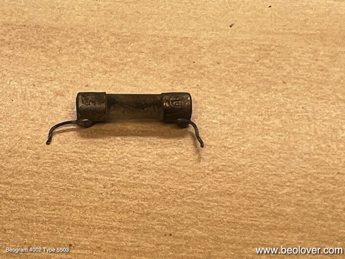
Like many AC-motor Beograms this one also had a 'troubled' fuse F1. It is directly soldered to the PCB. I extracted it:
I measured its resistance, yielding ~13 Ohms. Way too high. So I replaced it with a new one. I had to solder the wires to it:
This shows it implanted:
Another weak point of the AC motor Beograms is the solenoid lever, which came with a riveted plastic extension for activating the solenoid current limiting switch. In all Beograms of this type that I came across so far, the plastic extension developed stress cracks around the rivet:
It is important to fix this since a missing extension will result in an overheated solenoid. I drilled out the rivet, which liberated the extension. This shows the separated parts, as well as my 3D printed replacement ready for bolting on:
This shows the replacement extension in place:
This shows the repaired arm in action. It properly activates the solenoid switch:
Finally, I also replaced the as usual hardened damper gasket with a new one:
This ensures a consistent arm lowering experience. 
This Beogram is now updated to the latest 'Beolover restoration standard'! I will play it for a bit and then it will return to its owner in California.