Featured Post

Beolover SyncDrive: DC Platter Motor Replacement for Beogram 4002 and 4004 (Type 551x and 552x)

Late Beogram 4002 and the 4004 (Types 551x and 552x), which have DC platter motors instead of the earlier synchronous AC motors usually suff...

Monday, October 12, 2015

Beomaster 8000: Fault Switch Gets Triggered by Disconnected PTC Thermistor

Oh well...I guess I was a bit too enthusiastic when I declared victory in my last post about the output amplifiers of the Beomaster 8000 that I am restoring right now. It turned out that there was an intermittent issue that triggered the 'fault switch' and that in turn turned off the relays that enable power to the output stages. Here is the relevant circuit as shown in the Beomaster 8000 'Technical Product Information' booklet:

Here is how it works: TR16/17 form a latch that is triggered by a >~1.5V voltage coming from the "fault output" of the output stages between R254 and R253. When the latch is set it turns on TR15, and 15V apply to R68. That pulls up the base of TR11 and it turns on, which in turn turns on TR12. This pulls up the base of TR18 and the relay looses power. This cuts the power to the output boards, and the 8000 goes silent. All other circuits remain on, i.e. the display are functioning normally etc...

The two failure modes that can trigger the latch are:
  1. A DC voltage at the 'AF OUTPUT' (this usually means that one or more TIP transistors burned out due to overload or failing quiescent current trimmers
  2. The heatsinks get too hot. This increases the resistance of the positive temperature coefficient (PTC) thermistor that is connected to the junction between R353 and R252 and GND. When it is cool it has about 50 Ohms which pulls the fault output to GND. If the resistance increases, a DC voltage develops due to the pull-up to 55V and the latch is triggered.


In my particular case, the receiver came on, played for about 30 sec on the left channel and then it went silent. One could also hear three clicks in rapid succession right after starting it up, which is one too many. Normal are two clicks, which correspond to the start-up sequence during which the two relays that control the current into the toroidal transformer get switched in succession to limit the inrush current into the transformer. The third click meant that the fault mechanism turned the relays off again. In the beginning I was a bit confounded by the fact that the left output was continuing playing for half a minute. It turned out that this is possible due to the charge that is in the reservoir capacitors, i.e. it shut down when the voltage dropped close to zero in these capacitors. Why it did not do that on the right side, comes from the fact that the right supply also powers the preamplifier via an attached ±30V supply. This causes the charge on the reservoir caps on the right side to dissipate more quickly.

Since the output stages showed perfect current values during my test with external power supplies, I first thought that the fault switch itself was at fault. So I tested it by grounding the fault output from the output stages, and this caused the issue to disappear.
Note: This test needs to be performed from a cold start, since the latch in the fault switch only resets when the 15V rail turns off, i.e. the Beomaster needs to be turned off for that. However, the Beomaster runs a turn-off sequence after pressing the off bar on the keypad, where the 15V remain alive for another 60-90 sec. This means that one needs to wait a couple minutes before turning it on again to see if the grounded fault output disables the fault condition.
In my case this test yielded a functioning fault switch, and therefore the issue had to be in one of the outputs! It turned out that the left stage had a PTC that was intermittently disconnected from R253/R252, which caused it to loose its ability to pull the fault output to zero at normal temperatures. The picture shows the broken white-blue striped lead that connects the PTC (which is mounted on the heatsink) to the fault switch voltage divider. The tricky part here was that the lead looked perfectly o.k. since it was attached by the insulation to the solder terminal and the lead was only broken off in the inside.

After restoring this connection, the Beomaster started working normally.

Saturday, October 10, 2015

Beomaster 8000: Rebuilding the Outputs, A New Interesting Output Failure Mode, and First Startup

I started working on the Beomaster 8000 that I recently acquired via eBay on behalf of an B&O enthusiast in the UK. The 8000 is definitely one of my most favorite restoration projects. An absolutely awesome design. The Beomaster 8000 was sold under the premise to be fully working but to have had some 'amplifier trouble', which supposedly had been 'professionally' repaired. Oh well, I heard such claims before, and especially on eBay the unsuspecting buyer needs to be aware that there are not many repair outfits left who can or want to tackle these units. Instead there is a lot of amateurish effort going on with the aim to make a fast buck and turn these sought-after units around for a ransom 'in restored condition'.

With that in mind I approached this Beomaster with caution and gave it my usual 'fix outputs first and then turn it on' treatment. So I opened it up and found a fairly clean situation. However, three screws are missing under the speaker switch cover:
And the cardboard shield that is supposed to keep the solder points on the display board from shorting against the toroidal transformer was installed incorrectly:
An interesting feature is the late-series microprocessor board that has soldered on EMI can lids and a sticker that says 'Sealed unit. To be returned to the distributor for service'...we'll see to that...;-)

After I lifted the display/uProcessor boards into service position and took the input socket panel tray out I looked at the output PCBs. And I made an interesting find: The quiescent current trimmers were replaced on both channels with 47 Ohm resistors. A very creative, but questionable fix to the corroding trimmer problem that commonly leads to frying the transistors in one or both outputs when the trimmers go open circuit. Here is a picture of the left channel board:

The resistor in question is in front of the third electrolytic cap from the left. Very crafty! I hooked the right channel board up with three external power supplies providing the ±55V rails and the 15V control bias:

The multimeter shows the voltage across the two emitter resistors R236/7 as 4.7mV. This is much lower than the prescribed 18mV. Well, at least the 47 Ohm resistor errs on the 'better side' by running the output Darlingtons IC203/204 at a too low operating point. Had the 'expert' who did this elected to use the next standard resistor value of 56 Ohms, most likely the unit would have run pretty hot. The problem with running at a too low operating point is that class B amplifier cross-over distortion is introduced in the output signal since the two half-waves are not 'connecting' smoothly at the cross over point. Since all TIP141/146 pairs are slightly different, trimmers are needed to find the perfect operating point for each unit independently. 

I installed as usual 25 turn encapsulated 100 Ohm precision trimmers
in both of the output boards and also exchanged all the electrolytic capacitors with 105C level quality Japanese units. This shows the left channel:
And here is the right:
Then I ran the right board with my external supplies and adjusted the trimmer to yield 18mV across the emitter resistors:
The power supplies showed the usual 0.11A (-55V), 0.1A (+55) and a close to zero current on the 15V control voltage pin


Very good! Then I did the same for the left channel, and I was surprised: No matter to what value I would set the trimmer, the multimeter would show zero voltage across the emitter resistors. Something was not working!
I poked around and measured the voltages across the TIP141 and TIP146 'columns' in the output. The voltages seemed reasonably close to the values shown in the service manual. Very strange! Then I measured the voltage at the base of the npn Darlington (IC203) while turning the potentiometer. Nothing happened. It stayed constant at about 1V. This was strange, since the potentiometer is supposed to adjust this voltage to about 1.2V to set the operation point of the Darlington. I did the same at its pnp match (IC204) and this base changed the voltage depending on the trimmer setting. A bit of head scratching lead me to the root cause of this phenomenon: The yellow lead between the emitter of IC203 and the PCB was open circuit. I unsoldered the lead and found that it was only hanging on by a shred of insulation, but that the wire had disconnected:
I took some insulation off and soldered the lead back in, and then everything was as it should be.
Time to plug this baby in and finally turn it on:
Allright! First light! This marks the start of another Beolover restoration!


Thursday, October 8, 2015

Beogram 8000: Not Responding to Keyboard Input - Not Working Rotary Encoder Feedback

A Beogram 8000 hailed from Tokyo in search for some TLC. It was initially purchased from ebay and supposed to be in excellent condition. Once unboxed, however, it turned out that the unit did not work properly. There is already an extensive thread on Beoworld.org about the issues this unit displayed. In a nutshell, when pressing start the arm would run to the end of its range and then be stuck.
Yesterday, I opened the unit up and had a look. I immediately suspected a fault with the rotary encoder that is fitted to the spindle that drives the carriage with the arms. In difference to the earlier 400x models, the 800x employ a more modern positioning concept that is based on detecting the angular motion of the spindle and calculating the carriage position from that. This is a concept that is used in most modern control systems involving motors. The encoder unit is very similar to the ones used in the Beomaster 8000 for the volume and FM frequency wheels.
In the Beogram 8000 the evaluation of the encoder signals is done by the microcontroller, which has two inputs that detect the intensity fluctuations on two sensors. The fluctuations are generated via an aperture wheel that sits between the detectors and the IR emitter. Depending on the phase of the fluctuations on the two detectors relative to each other the system can detect the direction of the motion. The number of intensity oscillations tell the traveled distance. This way, the microcontroller always knows where the needle is. This 'feedback' is used to determine where to set down the arm, when it is time to lift and return home etc...
Therefore, when there is no feedback, the controller does not know anymore where the arm is. The firmware seems to be programmed with simple if...then conditionals that cause action depending on the position. If the position does not change in the mind of the controller (in the case of a non-working encoder system) the arm simply continues to travel until it hits the mechanical stop at the end.

All this suggested to me that I needed to investigate the encoder system to get to the bottom of the issue at hand. Below is the relevant section of the circuit diagram. Since I had similar problems already a couple times with Beomaster 8000s that I restored, I first checked on the functionality of the light detectors and the IR diode (OPE1). In the Beomasters the diodes had failed.

With the multimeter I determined 1.2V at the anode of the diode and this told me that it most likely was o.k. (they usually die by going OC). Then I measured the resistance on the photoresistors. They both showed about 1k when shining a strong LED light into the assembly and about 20-40k when just room light trickled into the setup. This seemed o.k., too. 

So I hooked up my oscilloscope and measured at the P2/6 and P2/4 whether I got pulses when manually turning the spindle. Of course the deck needs to be in PLAY mode or another on state to have things powered up. I had it in PLAY with the carriage belt removed, so the motor simply ran but the spindle did not move. This measurement yielded pulses for both encoder channels. The next step was checking the outputs of the opamps. And there I found a first clue to the problem: IC2 had no pulses at the output, while IC1 gave me nice 5V square pulses.
So I had a look at the PCB, and there it was:

The input of IC2 was short circuited to GND. In the above photo that is the IC pin that is associated with R5. It connects to the adjacent GND pad on the left via a gigantic solder ball. In fact if you look at the entire area it is apparent that someone with very little practice in electronics messed around and did some 'expert work'. Another great example of a 'perfect condition' or 'fully restored' ebay unit....(I hope this guy will smolder for a long time in Vintage Hifi Purgatory when his time comes).

Grounding the IC2 input of course results in a zero output signal since then there is nothing to amplify, and that explained my measurement. I fired up my Hakko desoldering gun and removed the solder from the pads and then resoldered them:

And this did the trick. The unit is working again. I put on my least favorite record (Sam Rivers) that I use for this type of testing, and pressed PLAY. The arm moved to the lead-in groove and lowered. Cueing worked and STOP. Very good!


Beogram 4002 (5513): Adjusting the Floating Chassis Height

Once the main platter bearing is adjusted in a Beogram 4002 (5513), the floating chassis height needs to be set in a way that the aluminum surface of the platter is flush with the surrounding aluminum panels. This adjustment is done by turning the nuts that define the height of the leaf springs that keep the chassis suspended for vibration insulation. This is best done with a 8 mm hex wrench bit:

Simply turn it CW to lift the chassis or CCW to lower it. This needs to be done repeatedly for all three of the springs until the platter is flush with the aluminum panels all around. I recently made a video that shows this process on a Beogram 4000. The difference here is that the 4002/4004 models do not have a counter nut, i.e.one should put a dab of paint on the nuts to lock them in place once the adjustment is satisfactory. If the platter is not centered in the aluminum panel (do this with the belt in place) then the position of the chassis can be set by bending the threaded rods on which the nuts sit. This is a bit a dicey operation where some relatively brute force needs to be applied with high precision. Nothing for the faint of heart!

This shows the end result. The platter is fully flush and looks just gorgeous!:

Here another angle showing off the lovely restored keypad:

Aren't they beautiful, these babies?? This is Beolove!


Wednesday, October 7, 2015

Beogram 4002 (5513): Restoration of Worn Keypad

I am approaching the detail&beautification stage of the Beogram 4002 (5513) restoration that I am currently doing. This Beogram has (like 90% of them) a worn keypad. The original coating simply is not up to the stresses presented by skin chemistry containing acids and fats. Usually at this age if the deck has seen even only moderate use the pads show ugly finger smudges. I recently had some pads refurbished by a beofriend in Denmark to have them on hand when needed for restorations (I'd be happy to get you in touch if you want to get your keypad rebuilt!)

Here are a few impressions. This is the original worn keypad:

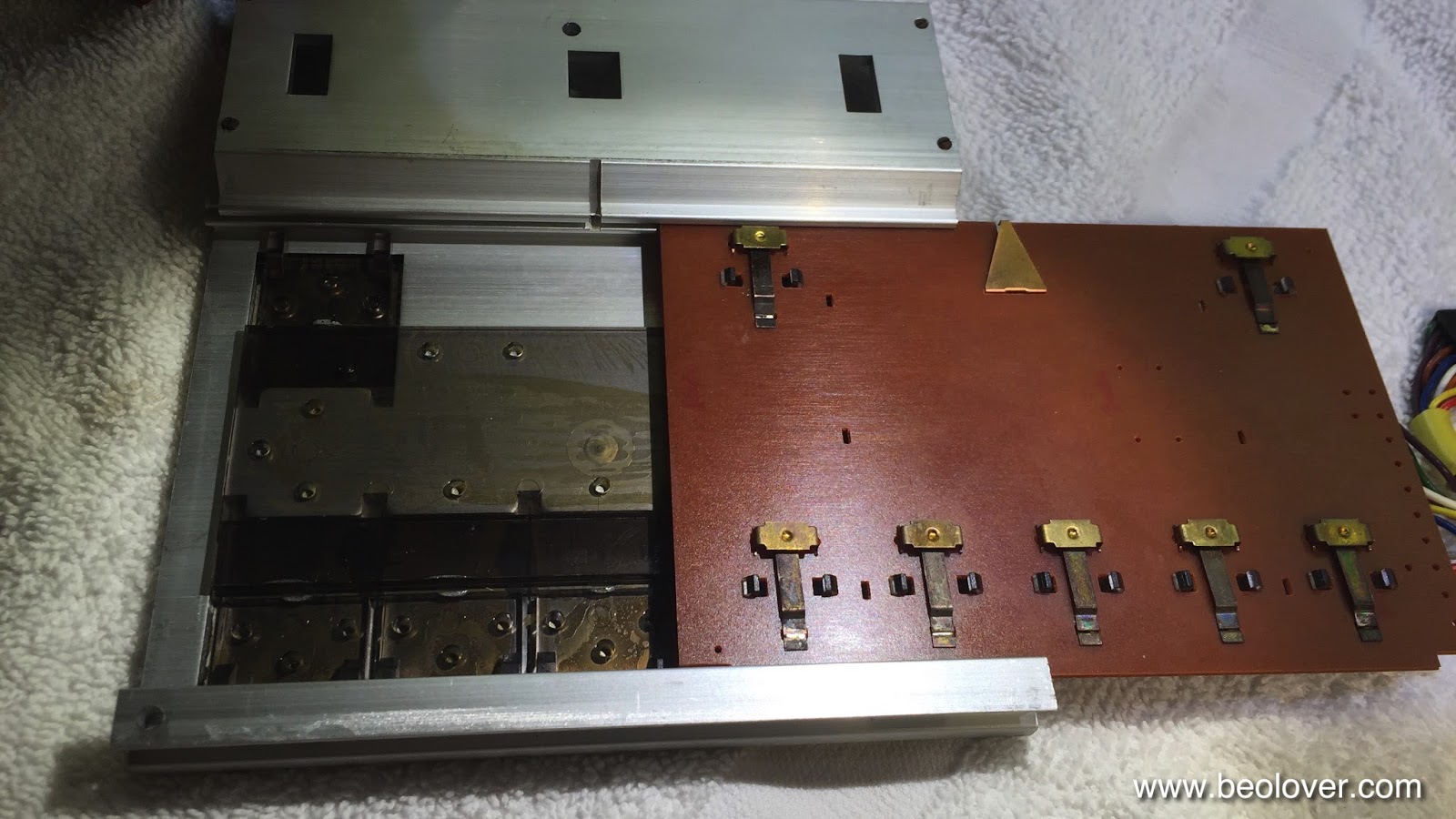
I needed to switch over the PCB that carries the actual switches, hence this was a good moment to refreshen the contact pads. I usually give them a light sanding with 2000 grit paper and then a coat of DeoxIT D100 to prevent further oxidation if they are not bent (if they are one needs to extract them, straighten them out and solder them back into place):

Then it was time to slide the PCB out of the original keypad:

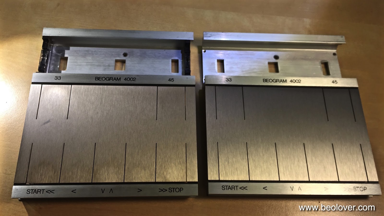
Here is a comparison between old and rebuilt:
And after installation:

Doesn't my friend do an amazing job?? They really look very close to new! Like traveling with a time machine back to a B&O store in the 70s and picking one up!


Tuesday, October 6, 2015

Beogram 4002/4004: Replacement of a Broken Cable Clamp/PCB Holder

The Beogram 4002 (5513) that I am restoring right now had a cracked cable clamp/PCB holder that needed replacement. This gave me a chance to put a part file to work that a Beofriend from New Zealand sent me in exchange for at-cost access to my Shapeway Store parts. I recently had it manufactured at Shapeways since I wanted to test it before adding it to my store inventory. 

Here are a few pictures. This shows the broken clamp:

Here is the replacement part printed in white together with the original broken part:

And this shows it after installation. It makes a nice fit with the PCB and holds it tightly in place while giving the audio cable the support it needs to stay put:

After this successful test, I made the part available to other B&O enthusiasts at my store:


Beogram 4002/4004: Replacement of Decayed Transport Lock Bushings

About 50% of all Beogram 4002/4004s seem to have decayed transport lock bushings. A while back I developed a 3D printed replacement part that can be inserted without needing to disassemble the chassis. The part is available in my Shapeways store. Here is a picture of a set of three bushings (you will need 6 parts. Two make up one complete bushing (See below for a link to the installation video).


The Beogram 4002 (5513) that I am currently restoring also had this problem. When I took it out of the box, the telltale orange fragments were all over the place. So I replaced the fragmented bushings with my 3D printed replacements. Here are a few pictures of this effort taken while I worked on the lock next to the carriage servo motor.
This shows the orange fragments and the lock before I fixed it:

Here you see the remnants of the original lock as it crumbled out of the mounting hole:
After cleaning all the debris, I inserted the lower bushing part:
Then I added the top part:

And then put the lock screw in place together with the mounting plate:

This procedure needs to be done for all three transport locks. When I designed the part, I also made a short video about installing the bushings: