Featured Post

Beolover SyncDrive: DC Platter Motor Replacement for Beogram 4002 and 4004 (Type 551x and 552x)

Late Beogram 4002 and the 4004 (Types 551x and 552x), which have DC platter motors instead of the earlier synchronous AC motors usually suff...

Showing posts with label removal. Show all posts

Saturday, May 21, 2022

Beogram 4000: MMC Cartridge Mount Restoration

I recently received the tonearm of a Beogram 4000 located in Western Australia. Like in many Beogram 4000s the MMC cartridge mount had broken off.

This Beogram still had the 'old style' tonearm, that elegantly plugs into the base of the arm, instead of featuring soldered signal wiring. However, this makes it more difficult to replace the MMC mount since the insert that goes into the aluminum profile tube has an adapter at the rear that has spring loaded contacts that 'grab' the circuit board that reaches into the back end of the arm to make contact. This shows the sad condition of the MMC mount as received:

The first step of any MMC mount replacement is removal of the broken one. They are usually glued into the arms. Luckily, the glue softens when the arms are 'cooked' for 30 min or so. I heated this one together with the also broken one from a Beogram 4000 from the UK that I am restoring right now:

Replacement of the MMC mount is part of my standard Beogram 4000 restoration package since all mounts seem to be quite brittle at this point in time, and it is an unpleasant event if the broken off tab sticks deep in a cherished $800 rebuilt MMC20CL...This shows the liberated insert after the cooking process:
This is the 3D printed replacement part with installed flex-PCB based contact traces:
The back part with the plug-in contacts mounts onto the thin tab at the end of the part:
This shows the signal wires soldered to the new mount:
And this picture shows all the component put back together. I was able to re-use the bottom part of the mount with the grounding contact for the cartridge housing:
After checking all leads for continuity (sometimes these thin wires can be broken inside the insulation) the next step was inserting the assembly into the arm tube:
I put a bit of white wood glue on the sides of the insert when I push it in to make sure it stays put when cartridges are mounted/pulled off. The defunct cartridge makes sure that the front end components of the assembly are positioned correctly to receive cartridges without any gap between housing and arm tube:
And this shows the final result of the operation:
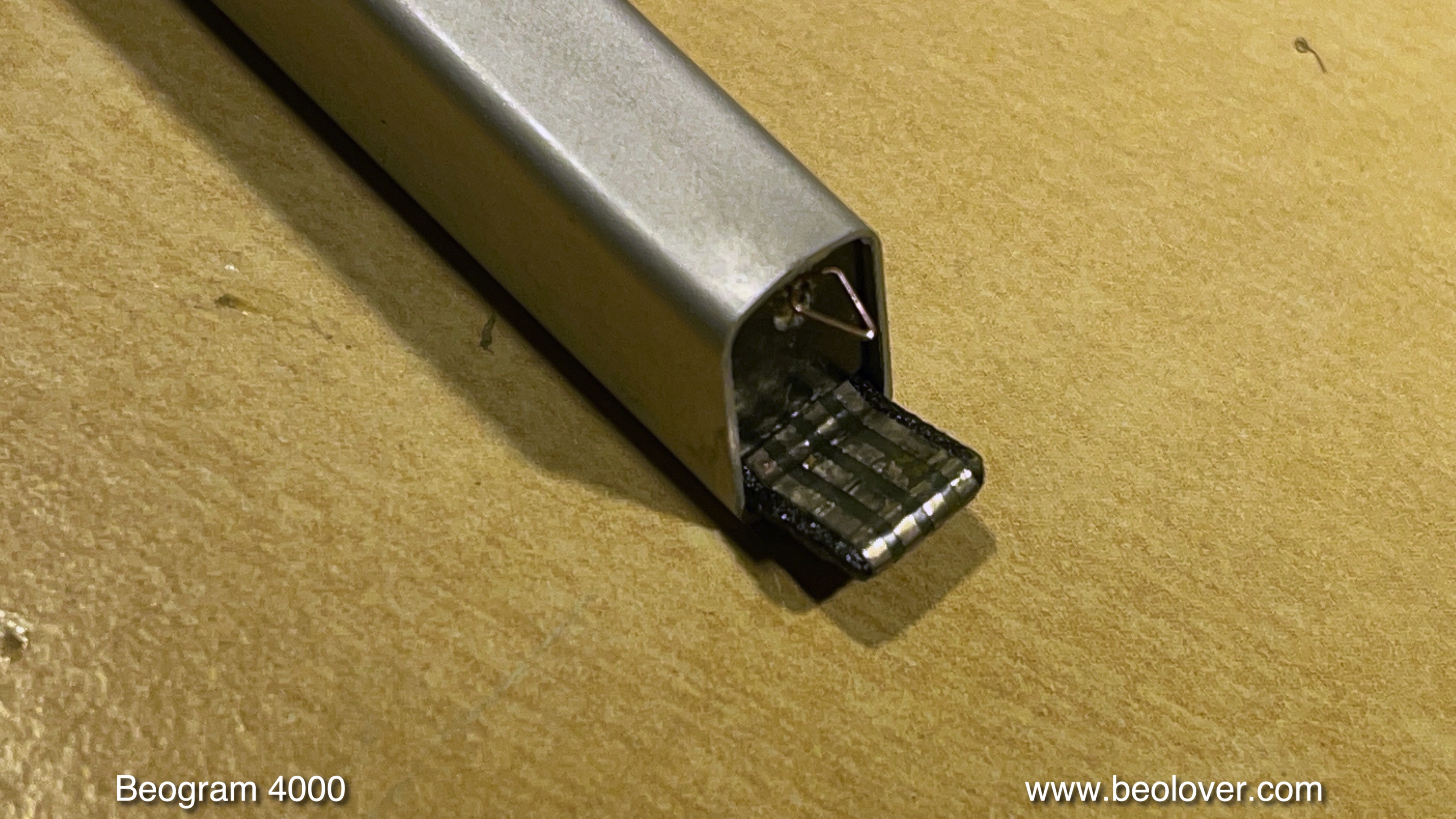
This tonearm is ready to travel back to Western Australia!


Friday, May 13, 2022

Beogram 4002: Plexiglass Hood Restoration

The Beogram 4002 (5523) that I restored recently came with a fairly scratched up hood. The good news was that the hinges were not cracked, and that the inside of the hood was almost undamaged. Only a few cleaning 'swirls'. So it was worthwhile trying polishing the hood back to a decent appearance. This shows the hood like it looked when I received the Beogram:

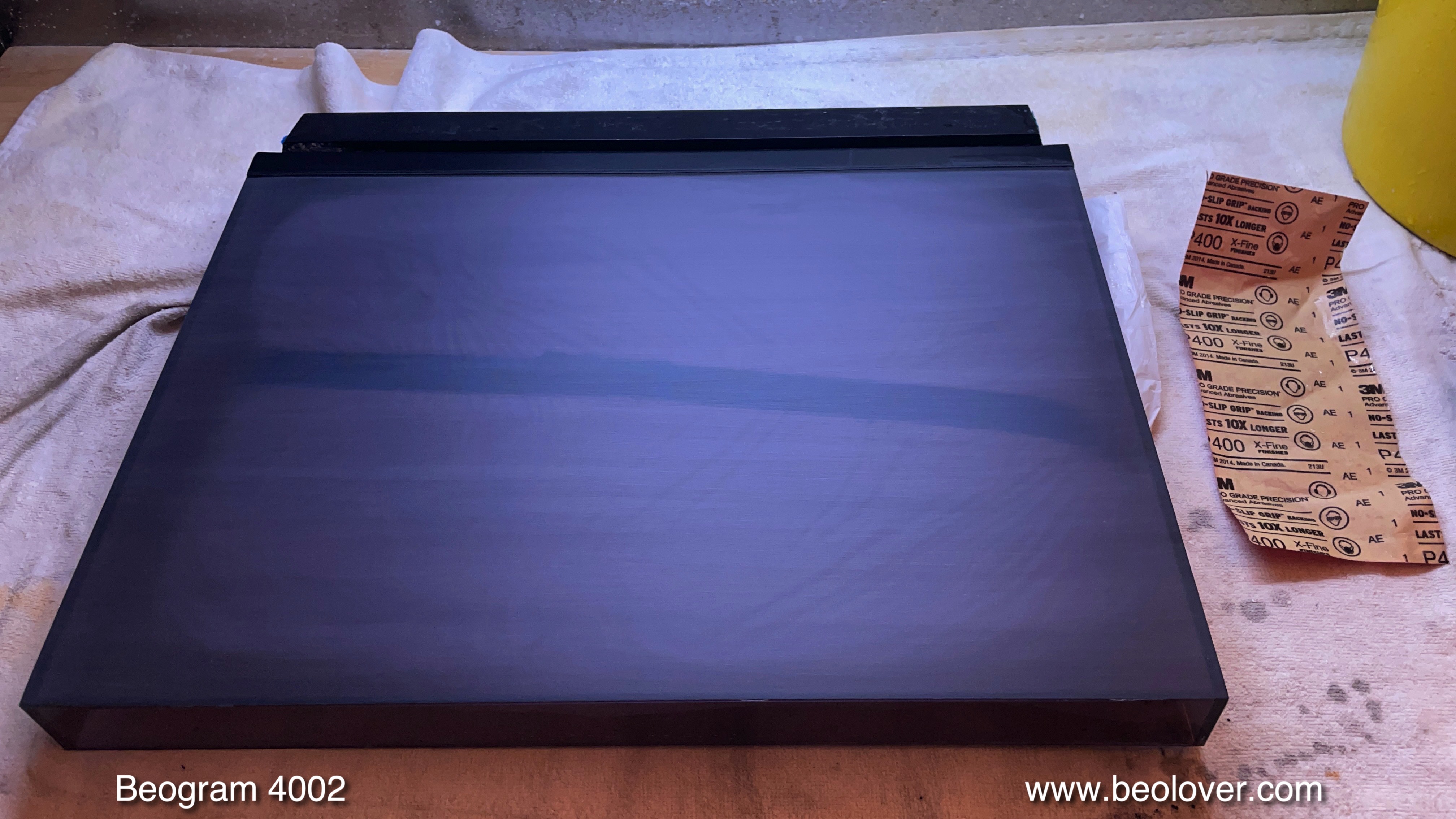
Since some of the scratches could be felt with a fingernail, I started with a 400 grit sand paper and 'equalized' the surface:

This removed all the bigger scratches along with the light ones and turned the hood into a matte, but homogenous surface. This is the usual starting point for polishing it back with ever finer sandpaper. After my usual 7 steps the hood was translucent again and looked pretty decent:

Of course, such polishing efforts are never perfect, and such a hood will never look like a newly moulded one. But this definitely looks much better than the original appearance!

Most 400x hoods have missing rubber bumpers that were supposed to soften the noise when the hood drops by its own weight onto the wood plinth. This shows one of the worn off bumpers. Usually there is still some rubber left in the mounting holes:
Before installing new rubber, the remnants need to be removed. It works well using a 2 mm drill bit for 'drilling' the degraded rubber out of the holes:
After this step it is time to install new rubber. I usually use snippets from 2 mm O-rings that I glue into the drilled out holes with super glue gel. Once the gel has hardened, I cut the snippets to a 1 mm length relative to the Plexiglass surface:
This gives the hood the original smooth 'plonk' sound when it is dropped by its own weight. Beolovely!


Monday, September 21, 2020

Beogram 4000: Replacement of Broken Off MMC Cartridge Mount with 3D Printed Replacement Assembly

I recently received the tonearm of a Beogram 4000 from Belgium. It had a broken off MMC cartridge mounting tab. Sadly, this happens to many Beogram 4000s since they used a plastic that seems to go brittle over the years. Luckily this Beogram 4000 has the old-style MMC adapter insert that connects via spring terminals to a narrow circuit board that sticks in to the arm from the back. This allows easy removal of the arm by just removing one screw and pulling it out. This shows the arm as received:


The plastic tab that inserts into the MMC cartridges is missing and only the flex PCB with the contact traces remained:

It turned out that the plastic insert was glued into this particular arm. This meant I had to simmer this arm for an hour in boiling water in order to soften the glue. After I removed the arm from the hot water I was able to push the assembly out from the back with a rod that fits snugly into the arm. This shows the extracted part:
Luckily, the lower part of the MMC mount with the grounding tab was still intact and could be reused:
The next step was to assemble the replacement part. The first step was to glue the new nickel and gold plated contact traces into the 3D printed plastic part replacement, and transfer the wires over:

Then I assembled the insert. I used a damaged cartridge for positioning the lower part with the grounding tab that it was flush with the installed cartridge. Then I glued the back part with the spring contact tabs onto the 3D printed part:
This shows the back contact tabs after assembly:

The next step was to insert this assembly into the arm in a way that the mounting screw would go straight into the back part while ensuring that the cartridge was snug with the aluminum tube. This was the result:
This is how the MMC mount looks like without cartridge:

Pretty close to the original! This arm is ready for duty again!


Monday, August 10, 2020

Beogram 4000: Replacement of an 'Old Style' MMC Cartridge Mount with a New 3D Printed Assembly

The Beogram 4000 that I am currently restoring also had a cracked MMC cartridge mount. Unfortunately, this is a problem common in many Beogram 4000 since the plastic B&O used for the cartridge mount seems to get brittle as it ages. Later Beogram 4002 and 4004 have cartridge mounts made from a different plastic, and it rarely happens that they break.

The first step was to remove the tone arm to be able to push the plastic assembly out of the arm from the back. Later 4000s have a mount that is glued in and one can remove it by 'cooking' the arm for a while in boiling water to soften the glue until one can push the mount out. More details about this procedure is posted in this blog post.

This post is about doing this replacement for an 'old style' arm, where the mount assembly is bolted into the aluminum profile of the arm. This shows the back end of the arms. The tone arm up front can be removed by taking out the screw that holds the aluminum profile to the arm base:

Then the arm can be pulled out:
Do this carefully, since there is a little spring on the excenter that allows adjusting the arm forward and backward (there is a small plate on it, that has already been removed in the above picture, but is shown in the 2nd picture below under the arm). 
Once the arm is off a small PCB is revealed that makes contact to the MMC mount assembly in the front end of the arm:
Turn the arm around, and the screw that holds the cartridge mount assembly in place can be accessed:
I removed the screw, and then carefully pushed the plastic assembly out from the back of the arm using a 8 mm diameter rod with a smooth end (to not damage the back end of the assembly) that fit into the aluminum profile. The extracted parts are shown in the upper part of the picture below:
The assembly consists of three components: (1) A 'carrier' that also has the tab (broken off) onto which the cartridge is stuck. The tab end of the carrier carries the flex circuit board that has the four traces for making contact to the coils of the cartridge (it came off due to the broken of tab). (2) A separate part that carries a grounding tab to make contact to the metal body of the cartridge, and (3) a part in the back that makes the connection to the PCB reaching into the back of the arm.
Below the extracted parts, the new plastic parts that I designed for this repair are shown. They were printed at Shapeways in black PA12 plastic, which is a sturdy engineering plastic that has a bit of flexibility while also being pretty stiff. Perfect for a cartridge mounting tab that is not supposed to break off when it is torqued a bit.

Since in this case also the grounding tab was damaged, 
I needed to design a replacement for this component, too.
The challenge was to find a suitable metal strip for fashioning a suitable grounding tab. After a bit of head scratching I had the idea to use an 'ammo pack' strip from Molex-style connector terminals:
I removed the terminals and plated the ammo strip with nickel and then with gold. Then I cut a small part off and bolted it into the 3D printed plastic part and bent the end into a suitable tab shape:
The next step was to glue a new flex PCB strip with the coil contacts (also Ni/Au plated) into the business end of the carrier part:
Then it was time to transfer the wiring:
After the soldering was done (use a small tip and be quick not to damage the plastic parts), the insert could be assembled together with the original back end part:
For assembling the ground tab part with the carrier, it is a good idea to stick a cartridge on it, which allows aligning the ground tab part with the back plate of the cartridge. I fixed the ground tab part in place with a dab of super glue gel on either side. The back end was glued on with contact cement (like in the original assembly).
And now came the interesting moment! Would this new assembly line up with screw hole in the arm tube when inserted into the tube?
Luckily it did:
While the cartridge sat snug on the end of the aluminum profile without a gap:
Perfect! This spared me another design iteration to make things match. It rarely happens that a part like this really fits on first attempt, but this time I was lucky! This shows the new cartridge mount with removed cartridge:
Beolovely! 

Time to put the arm back into its place:
A few more adjustments and it will be time to give this Beogram 4000 a first spin!


Friday, June 19, 2020

Beogram 4000: Hood Restoration - Exchange of Trim, Fixing Cracked Hinges, Spray Painting Corroded Metal Parts and Polishing

The Beogram 4000 that I am restoring right now came with a less than perfect hood. This hood 'had it all': Badly scratched plexiglass surface, corroded metal hinge parts, cracked plexiglass around the hinge area, and a wobbly plastic imitation aluminium trim strip (as it was standard on the early 4000). 

I set out by removing the plastic trim strip. Since it is attached with contact cement, I needed to bake the hood for a while in the oven at the 'warm' (~80C) setting. For this it is best to wrap it in aluminum foil to avoid hot spots:
After about 45 min in the oven
it was time to remove the trim. It can simply be pulled off from the warm hood. This leaves a bunch of contact cement residue behind:
This residue can be easily removed after soaking it in isopropyl alcohol for an hour or so. To do this I put isopropyl soaked paper towel on the glue
and covered it with aluminum foil to prevent evaporation:
After I wiped off the softened contact cement, it was time to fix the cracked hinges. Both sides had almost identical stress fractures around the bottom screw holes, a common issue with these hoods:
Since the cracks were still minor, this was a perfect application for my hinge patch kits, which consist of two patches and custom designed clamps that fit precisely on the patches:
This shows one of the kits installed, ready for plexiglass solvent to be applied:
The final result looks like this:

The patches are pretty thin, but they make the plexiglass a bit thicker, the price for having a stable attachment point for the hinge again. The application of the clamps causes some of the dissolved plexiglass to 'squirt' into the bolt holes, i.e. one needs to rout them out with a drill bit or similar after this repair process.
Now it was time to polish the hood, which looked like a used up ice rink after a skating competition:
I started out with 400 grit to remove the scratches:
This makes it homogeneously dull. After that the two hour process of polishing it back began. A nice workout in the garage!
I also repainted the corroded metal hinge parts:
This can be done fairly well by sanding the paint down and repainting the surface with black satin spray paint. This yields 'close-to-new' results:
After bolting the hinge back into the polished plexiglass hood, it was time to install an original Beogram 4000 aluminum trim, that I removed from a cracked 4000 hood (the result of a sad ebay experience with a seller who did not follow my packing instructions)
The application of contact cement to the hinge benefits from covering the area next to the strip with blue tape:
I brushed the contact cement on with a small cut to size foam block. It is essential to generate a smooth thin film. Otherwise the trim will be too high and not flush anymore with the hood.
Application of the cement to the aluminum trim strip is straight forward. When applying the strip to the hood, it is important to protect the contact cement from touching until the strip is moved into its precise location. This is helped much by placing a strip of parchment paper in between the strip and the hood:
Once properly positioned the paper can be pulled out and the strip pressed into the recess on the hood.
Since the hinge repair patches made the plexiglass a bit wider, it was necessary to conform the aluminium strip to the new shape. I did this with special clamps that I designed for these hoods a few weeks back:

They allow generating fairly high pressure on the strip, which creates a fairly conforming fit:
But a slight bulging due to the patches is unavoidable. 
The final step was to install new rubber bumpers on the front corners of the hood, to ensure a satisfying 'thunk' when closing it. I usually drill out the old degraded rubber with a 2 mm bit by hand, and then super glue a snippet of a 2 mm O-ring into the hole.
Trimming it to 1 mm length completes the installation:

And this is the final result:
Beolovely!