Featured Post

Beolover SyncDrive: DC Platter Motor Replacement for Beogram 4002 and 4004 (Type 551x and 552x)

Late Beogram 4002 and the 4004 (Types 551x and 552x), which have DC platter motors instead of the earlier synchronous AC motors usually suff...

Showing posts with label plug in ready. Show all posts

Sunday, April 23, 2023

Beogram 4002 (Type 5504): Installation of Commander Remote Control Module

This post discusses the installation of a Beolover Commander Remote Control Module in a Beogram 4002 (Type 5504) that I recently restored for a customer in Australia. This unit also already received an internal Beolover RIAA phono pre-amplifier.

This shows the commander Remote Module before installation:

The black three-wire appendage at the bottom is the IR receiver that gets fed through in-between the plinth and the enclosure of the Beogram (see pic at the end of the post) so the IR signal can reach the Commander Module. The narrow adapter board on the right is used to break the keypad contacts out for the Commander, that it can take over control of the turntable. The white wire harness makes the connection from this adapter to the Commander board. The red wired appendage on top is the auto-repeat indicator that gets bolted in with the keypad screw underneath the RPM adjustment panel.

Let's do the installation! This shows the keypad and the adjacent area of the main PCB where the Commander will be installed:
After removal of the keypad, the keypad PCB needs to be slid out of the keypad assembly. This reveals the solder terminals where the main PCB connects to the keypad:
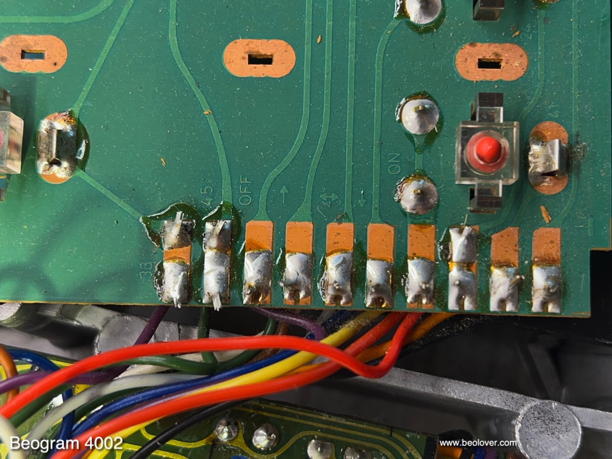
For installing the narrow adapter board part of the solder needs to be removed to generate a smooth and flat 'landing strip' for soldering the adapter in. This is shown here:
I used a de-solder pump to remove the solder.
The next step is to place the adapter on this cleared area and solder it to two of the pads, preferably on either end: 
Tacked on like this the adapter pad can still be aligned and oriented properly.

***Note added in proof: After having installed this component a few times, I realized that it is best to solder the adapter into a position where the white plug socket is flush with the board edge. There are some keypads where the plastic part underneath the keypad is in a position that is a bit further to the left than normal, and it can interfere with the adapter if it is soldered too far inside the board perimeter).*****

Once it is in place (i.e. orthogonal to the solder pads, the solder pads match up well with the pads on the keypad PCB and the adapter sits flat on the pads with only minor gaps), then the remaining pads can be soldered:
At this point it is a good idea to plug the white wiring harness into the jack on the adapter board (support the PCB on the back of the jack while pushing the plug in):
If you do this at home, be careful to put the plug in in the right orientation. It is easy to bend the contact terminals in the jacks due to the miniature size of these connectors. This concludes the keypad modification. From here on it is plug-and-play. The next step is bolting in the auto-repeat indicator under the RPM indicator panel:
The red wiring harness is supposed to 'leave' the keypad via the cutout for the RPM panel wiring on the left. Now it is time to bolt in the Commander board. It simply bolts to the PCB screw that is next to the keypad with the included longer screw that replaces the original screw the Beogram came with.
Once the Commander has been bolted in it is time to make the wire connections. This shows the plug of the white harness. The way it needs to align is like shown here, with the connecting terminals on the upper end of the plug. Another indicator of proper alignment is that the white wiring goes 'flat' from the keypad adapter to the Commander board. If it is twisted, the orientation is probably 180deg off.
Once it has been carefully plugged in, the red harness of the auto-repeat indicator gets plugged in. Then the IR received needs to be threaded through the gap between plinth and Beogram enclosure:
There is a gap between the metal parts that are glued to the plinth, and that is where the IR wiring should go through. If done properly, the IR receiver will stick out like this from underneath the plinth:
And that is it. Now the Beogram can be powered up and the remote control should allow starting the Beogram with the "start/arm lift" button. This is a summary of the commands that are available:


Wednesday, November 23, 2022

Beogram 6000 (5505): Installation of AC-Motor Version of Beolover Commander Remote Control

This post discusses the installation of the AC-motor version of the Beolover Commander Remote Control into a Beogram 6000 (Type 5505) that I just restored. These are the links to the initial three posts that discuss the initial condition of the unit, its functional restoration, and the restoration and exploration of the CD-4 channel pre-amplifier.

This Beogram 6000 has an original keypad that is in almost pristine condition:

An ideal case for installing the Beolover Commander! I developed it mainly as a way to protect the Beogram keypads. They tend to loose their coating if they are used with direct finger contact. So the best way to protect them is to not use them! The Commander allows full control of the Beogram without ever touching the keypad again. It even adds some more functionality: It has a programmable auto-repeat function and adds the 'spin the platter for record cleaning' that is a standard feature in later DC motor Beograms, but is absent in the AC motor versions.

This shows the the Commander system for the AC motor Beogram 4002 versions:

The Commander remote module is controlled via a paired Apple remote. The pairing function can be cancelled if so desired, or necessary for integration of the Commander into a larger remote controlled system. 

This is a summary of the Commander functions:

The main difference between the DC and AC motor versions of the Commander is that there is no keypad connector in the AC Beogram versions since their boards are mostly wired directly together. This means a connector needs to be installed on the keypad PCB before the Commander can be plugged in.

So the first step is the installation of this adapter. It is shown here:
The first step is to remove the keypad, flip it over, and then slide the PCB out. This is how the keypad looks flipped around: 

Unfortunately, the above picture shows the PCB already slid out partially. In its 'fully in' position, the alignment tab catches the machined groove in the aluminum profile to hold the PCB firmly in the proper position:
This tab is spring loaded, i.e. you can simply pull it up with your fingernails, and then slide the PCB out:

Before moving on with the process, it is a good idea to put the keypad into a secure location to make sure it does not get scratched accidentally.

For the installation of the adapter the PCB needs to be flipped over

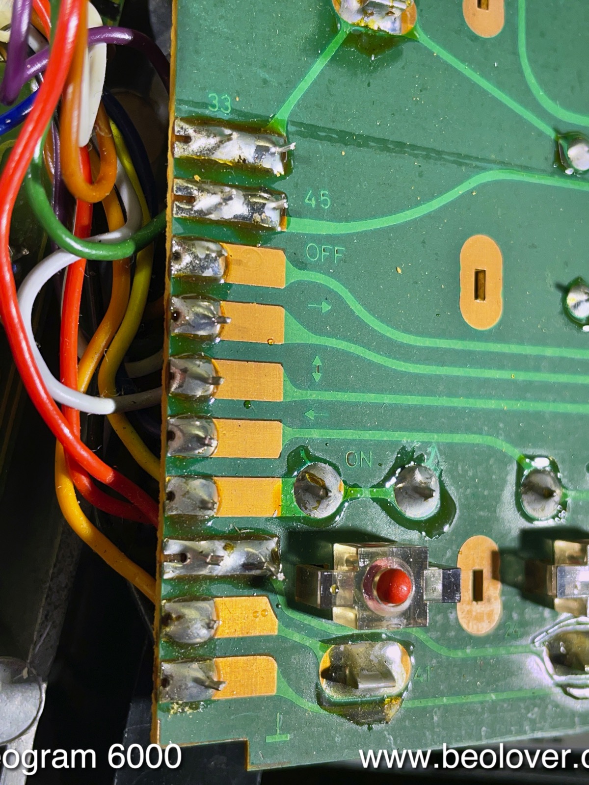
On the left side of the PCB there are the wire terminals. This shows them magnified:
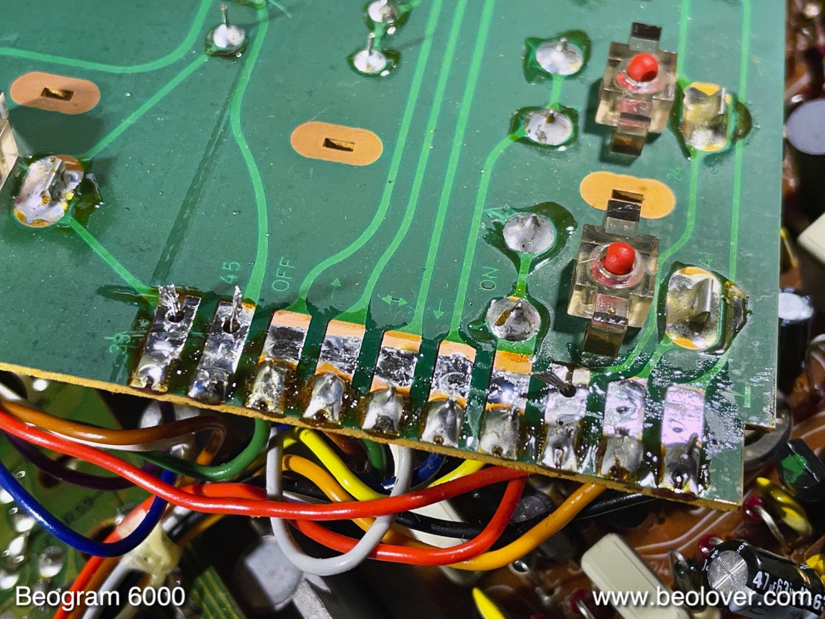
This is where the adapter needs to be installed. The first step is to create a 'corridor' free of solder through the center of all the wire tabs as shown here:
There are some wires that connect at the back end of these terminals as shown here:
Usually, there is no other way than to remove the solder from these wires when creating the flat area for soldering the adapter in place. After installation of the adapter these wires will need to be soldered in place again.
This shows the adapter soldered onto the terminals. It needs to be vertical relative to the PCB and the end of the white socket needs to be about flush with the boundary of the PCB. Like so:


I usually tack the adapter to the PCB on two of the terminals and make sure it is well aligned. Then I solder the remaining pads together. It is difficult to remove the adapter once it is fully soldered in. So better make sure it is in the right place before putting all that solder down.

The next step is the installation of the Commander board. This shows it from the bottom:
The part that connects to the main PCB is the narrow tab on the right side. The raised edge on the far right end aligns the board with the edge of the main PCB. The bolt hole on the left side is used to bolt it onto the main board using the threaded hole that is used for the right PCB screw of the main board. It is located between the two blue trimmers I installed for adjusting 33 and 45 RPM.
This shows the Commander board in place. The original PCB screw needs to be replaced with the included M3x14mm screw due to the added thickness of the Commander board.:
It is important that the black remote receiver is fed in between the the plinth and the enclosure next to the front alignment feature of the plinth.
Once the board is bolted in, the keypad can be connected with the included white jumper:
This shows the connection to the Commander board in more detail 
and this the connection to the adapter board
It is important to note that the installation of the white jumper needs to be done carefully, since it is easy to bend the filigrane contact pins inside the sockets. In other words, the connectors need to be aligned properly before they get pushed in. This shows everything from the top:
Now the keypad PCB can be slid back into the keypad profile:

The final step of the installation is mounting the auto-repeat indicator PCB under the screw that holds the keypad in place. Since this is a Beogram 6000 which uses the CD-4 indicator integrated in the RPM panel, I had to modify the little PCB by cutting out a corner with sheet metal shears. This opened a path for the light emitted from the CD-4 indicator LED under the keypad.

After this I put everything back together and tested the Commander system. I selected one of my favorite Bob James albums, 'Lucky Seven' from 1979 (Tappan Zee Records, Columbia, JC36056). Of course this album was thoroughly cleaned with a CleanerVinyl ProXL setup using a multi-frequency ultrasonic cleaner before listening! This shows the Beogram 6000 in action together with the nice cover of this album: 
Beolovely! Soon it will be time to return this Beogram 6000 to its owner in the UK.


Monday, October 30, 2017

Beogram 4002 (5523): Installation of 4002 Commander MkII Remote Control and Internal RIAA Preamp

I recently finished up the restoration of a Beogram 4002 (5523). My customer decided to add both the Beolover 4002 Commander MkII remote control receiver (it works together with a matched Apple remote) and the internal RIAA pre-amplifier. I developed these two upgrades a while ago. More information about their performance and installation is given on the 4002 Commander page on the blog and in this post about the development of the RIAA amp.  Both boards are available to other enthusiasts. Just send an email or use the contact form on the right. 

This shows the two boards together:
The board at the bottom of the picture is the Commander MkII remote receiver board. The MkII version comes with a repeat function, which uses the CD4 indicator on the keypad cluster as indictor. It is a plug-and-play installation. The board installs into the keyboard header on the main PCB and is bolted into place using one of the screws that holds the PCB down. 
The RIAA amplifier is soldered directly into the output relay solder points. This shows the output board as I rebuilt it with a new relay and grounding switch:
For the installation of the RIAA amp I needed to remove the relay and the switch again to make space for the board and the connectors. This shows the output PCB prepared for the installation together with the RIAA board upside down:
The red 3D printed component serves as spacer to elevate the board above the black in- and output board headers. This shows the board after installation:
The original headers are still accessible, i.e. the Beogram can easily be configured in its original way by plugging the cables into the original headers instead of the white amplifier connectors.
This shows both installed in the Beogram:


Monday, May 2, 2016

Beogram 4002 Commander MkII: Remote Control for Beogram 4002 Now With Integrated Auto-Repeat Function

The Beogram 4002 (5514) that I am currently restoring was supposed to receive my 4002 Commander Remote control system. A great idea, since the keypad is still near-pristine and the Commander remote will allow using the deck without touching the precious keypad. Check for demo and installation videos here if you are interested in upgrading your 4002. The Commander board plugs into all DC motor models. 

I decided to use this occasion to develop an updated MkII version of the 4002 Commander with an auto-repeat function, similar to what is found on the later Beogram 8000 and 8002 turntables. I realized that my long term goal may be to transform the 4002 into a deck that has the functionality of the 8002. Sort of a beautiful all-metal 8002....;-) 

This shows the 4002 Commander IR receiver board together with the red auto-repeat indicator board that utilizes the 4-channel "4-ch" indicator in the control cluster to indicate whether the single or the multi-repeat functions are active:
The 4-ch indicator was used in a few 4002s that have the CD-4 decoder board installed, which essentially turned them into a Beogram 6000. Most 4002s do not have this upgrade, and so one rarely sees this indicator in action. Well, now there is a way to enjoy it!...;-)

This shows the indicator in action:
And here an impression of the very simple installation process:
The indicator assembly plugs into the 4-channel indicator illumination slot in the aluminum panel and it is secured in place with the screw that is used to bolt down the keypad. My goal is always to keep the design of the Beogram intact that my upgrades can be removed without a trace if desired at a later point.

This shows the deck in action with the auto-repeat function engaged:
The 4-Channel indicator is on permanently if just a single repeat has been selected. If multi-repeat is active (up to 10 repeat plays) the indicator blinks in a 1s interval. As the plays are executed sequentially the indicator switches back to permanently on when only one play is left.

The repeat functions are selected by pressing the 'up' key on the included paired Apple remote at any time before or during the playing of a record. Each time the 'up' key is pressed the number of plays increases by one. I set the maximum plays to 10, thinking about a situation where the deck is set into action but then forgotten. So a mechanism that automatically turns it off after some time is a good idea. The 8002 has a similar restriction, and I think for the same reason. This is Beolove!