Featured Post

Beolover SyncDrive: DC Platter Motor Replacement for Beogram 4002 and 4004 (Type 551x and 552x)

Late Beogram 4002 and the 4004 (Types 551x and 552x), which have DC platter motors instead of the earlier synchronous AC motors usually suff...

Showing posts with label LDR test connector. Show all posts

Monday, January 23, 2023

Beogram 8002 Type 5633: Floating Chassis Restoration Tasks

I wrapped up the work on the Beogram 8002 floating chassis. It should be ready for some functional testing of the turntable operations in the next blog post.

Here is the floating chassis before starting the restoration work on it.


It has a bit of dust as you would expect but nothing major to clean up or repair.

I removed the center hub to inspect the tachodisc and speed sensor.


Next is the disassembly of the tangential arm assembly for inspection, cleaning and lubricating.
I will also check the arm raise/lower solenoid and mechanical parts. 


The arm lower/raise mechanics looked good.
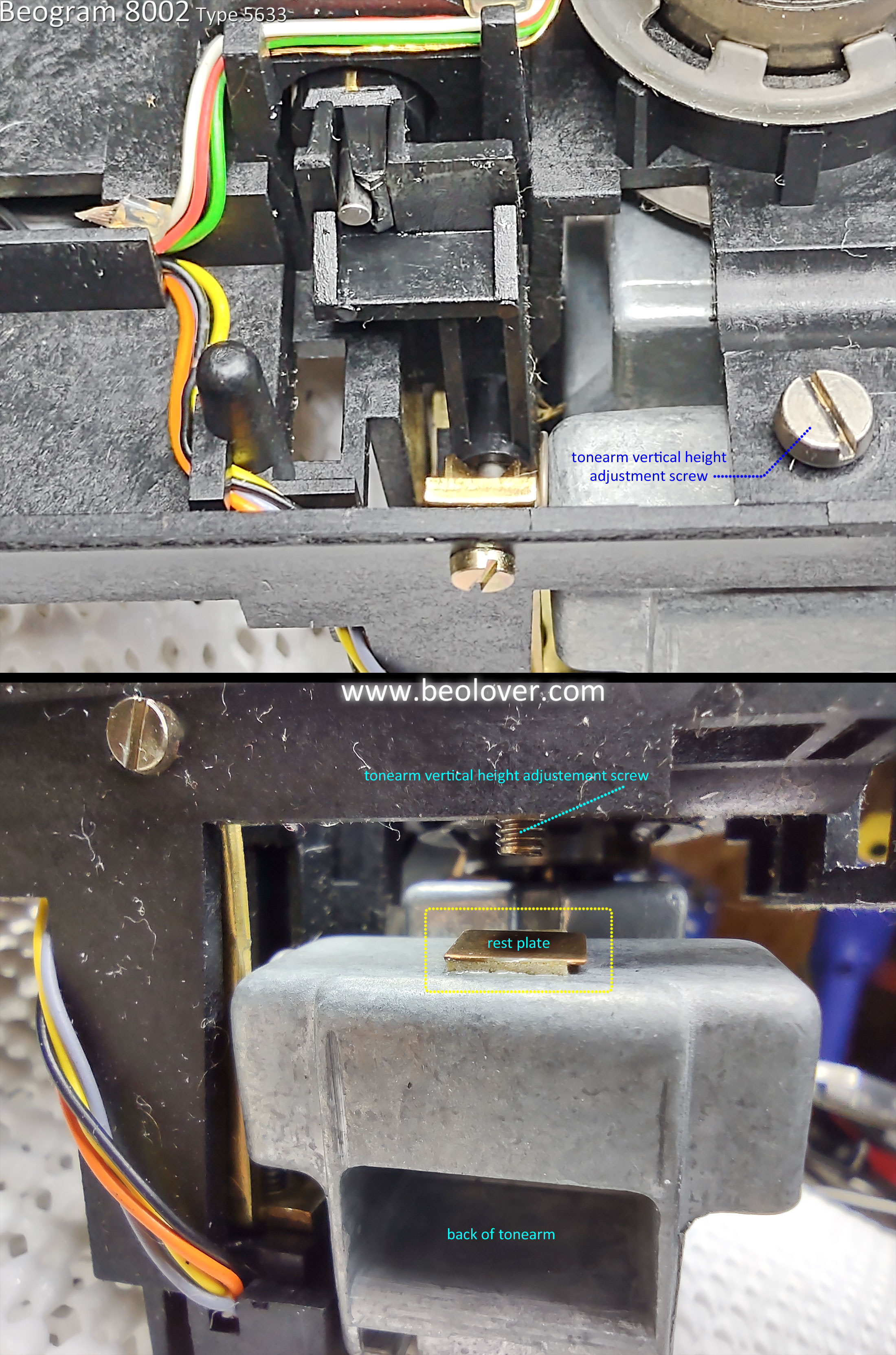
While the arm assembly was turned over I took the opportunity to align the tonearm height with the sensor arm.

Interestingly this Beogram 8002 unit has a little, square rest plate for the tonearm height adjustment screw.  Usually there isn't anything there to keep the screw from contacting the metal back of the tonearm.  That can cause problems with the arm lowering operation so I often have to place a small piece of Dura-Lar plastic there.  In this case, the problem is already taken care of.


Now it is time to clean the old oil and grease from the spindle, rails and attachment pieces.
Then re-lubricate everything and reassembly the arm assembly.


Because this Beogram 8002 was configured for the North America market the rear guide rail has rubber tip ends to dampen any vibrations from the 60 Hz line voltage.

I applied some rubber restoring fluid to the rubber ends when I reassembled the arm assembly.
For re-lubrication of the spindle I still use the original B&O combination of Rocol MTS 1000/2000  with Mobil NUTO H32 mixture. However, a good modern, synthetic oil will also work fine.  Just don't over lubricate the spindle where oil flies off when the spindle spins.  
On the shiny guide rails I apply either some M-kote DX Paste Grease or some Tri Flow Dry Lube.
At the pivot points of the spindle where it attaches to the chassis I use a little bit of Tri Flow Red Grease.
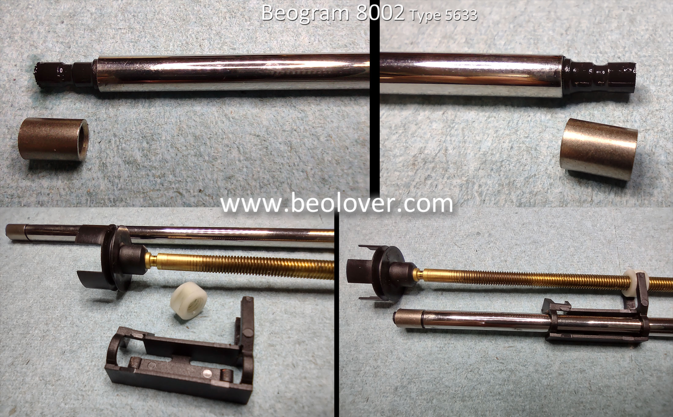


Here is the tangential arm assembly put back together with the tonearm aligned with the sensor arm.


There were a couple of electrical restoration tasks left to do that I didn't complete on the previous post.

One is the replacement of the phono muting relay.
I replaced the original muting relay with one I sourced from Beoparts.


I also installed my usual test connector for adjusting the LDR sensors that are used for the forward and reverse arm scanning operation.  It is kind of a pain to connect DMM probes to make the voltage measurement while adjusting the sensor aperture so I install a three wire test connector that allows checking (and adjusting) the LDRs without opening the Beogram 8002 into its service position.


The Beogram 8002 turntable components can now be assembled and tested.

Friday, May 14, 2021

Beogram 8002 From North Carolina: Finishing up the service manual adjustments

I was able to get quite a lot done since the previous post.

I performed the power supply tests, adjusted the tracking force by calibrating the tonearm counterweight, adjusted the tracking sensor setting and adjusted the forward/reverse scan LDR voltages.

To begin with here are the supply voltage checks from the supply filtering capacitors for +5V, +15V and -15V.


I also measured the regulated +5V that goes to various places in the Beogram 8002 (including the microcomputer board).


In this earlier post for this Beogram 8002 I had to fix the tonearm counterweight.
Now it was time to calibrate and adjust the tonearm for 1 gram of tracking force.
For the tracking force adjustment and the record tracking sensor adjustment that will follow I don't want the Beogram 8002 platter to rotate when the turntable is on.  To facilitate that I unplugged the P4 connector on the main PCB (with the Beogram AC plug disconnected as well of course).


The other test wires connected (temporarily) to the back of the main board are for monitoring some key Beogram 8002 signals with an oscilloscope.  I will make those measurements later in this post.

For the tracking force calibration and adjustment I installed a cartridge on the tonearm and set the tracking force to 1 gram.  Next, I adjusted the counterweight position using the set screw until my tracking force scale measure 1 gram.


Now that the tracking force is set I ran through the tracking sensor adjustment steps.
For this adjustment a test record is set on the platter.  The platter drive is still not connected so it can only be turned manually.

The procedure says to lower the tonearm with the cartridge stylus onto a record groove.
The platter is turned manually while observing the Beogram 8002 servo motor (tangential arm assembly motor).  The servo motor should advance the tonearm the first time within 2 platter rotations...plus or minus 1 rotation.  So between 1 and 3 rotations.  After that the servo motor will perform advances as necessary. It is a good idea to use the same test record(s) for this adjustment as the record grooves vary between vinyl records. Using the same set of records for the adjustment will allow the setting to be consistent.

The service manual refers to the tracking sensor adjustment screw as "screw B" shown here.
Note the tracking sensor lamp illuminating from inside its housing.  If that lamp is not on then of course replace that first.  I don't believe I have ever come across one that was out on a Beogram 800x turntable.


After a few iterations and the adjustment check performed on two different test records that I like to use, I was satisfied with the result.

I unplugged the Beogram 8002 AC plug and reinserted the P4 platter drive connector.
Then I plugged the Beogram back in and tested its play of a record.


One last adjustment is on the forward and reverse scanning control sensors.  The forward and reverse scanning buttons press a spring loaded aperture between a light source and an LDR. Two LDRs actually.  One for the forward scan and one for the reverse scan.  The change in the light through the aperture determines the scanning operation.
The steady-state (no scanning) voltages on those LDR sensors should be adjusted to around 620mV.
The adjustment for the LDR voltages is via a large screw at the back of the button panel. One for the forward LDR and one for the reverse LDR.


This is an important adjustment on the Beogram 8002.  If the scanning LDR voltage level is far enough off, the Beogram 8002 tonearm movement will not operate properly.

I have always found it very inconvenient to make this adjustment as it requires opening the Beogram 8002 into its service position. 

There are often cases where I want to double-check the scanning LDR voltage levels after the Beogram 8002 is reassembled in its cabinet.  Opening it all back up just for this measurement and adjustment is a pain.

For that reason I started installing a small test connector that I leave in the Beogram (both the 8000 and 8002 turntables).  With the test connector I can later make the measurement and adjustment again by only popping off the Beogram button control panel. It is easy to remove and reinstall.

Here is the Beogram 8002 button control panel removed for installation of the test connector.
The spring loaded aperture controls for the scanning LDRs are shown highlighted in the photo.


Here is the test connector I install.  The connector and its 30 gauge wiring will easily fit into the Beogram 8002 out of sight when the turntable is reassembled into its cabinet.


To use the test connector for the LDR adjustments I just plug in my three pronged test leads and make measurements with a DMM.

This photo shows the adjusted LDR voltage for the Reverse LDR sensor.


Very nice.  It is great to see the Beogram 8002 operating correctly again.

Now...while I have my test wires hooked up to the main board I collected some screen shots of the following signals at various modes of operation for the Beogram 8002.

The signals I wanted to observe are the Record Detection Sensor, the Platter Speed sensor and the two sensors on the tangential arm drive spindle.


Here are the oscilloscope measurements of those signals during various Beogram 8002 operating modes.

As a reference, here are the signals when the Beogram 8002 is off.


Here are the signals when pressing the Play button.


Here are a couple of pictures of the signals when the Beogram 8002 is returning home after searching for a record on the platter.  You can see that different patterns of bands on the Beogram 8002 platter affect the Detector Arm signal. Notice the difference in relative position between the two position sensor signals in these reverse direction photos and the previous, forward direction. They swapped positions on the oscilloscope trace.


Finally, here is a trace of the signals when a record is playing. This trace triggered on position sensor 2 in order to catch the activity by the servo motor advancing the tonearm. Note that the Detector Arm signal is silent as there is a record on the platter.  


It isn't a requirement to measure these signals during a Beogram 8002 restoration but I wanted to start collecting some reference photos to have in comparing the turntable restoration projects I have been working on.  They provide another visual reference of the turntable operation.

Tomorrow I will work on the Beogram's dust cover hinge repair. 
After that it will be ready to reassemble and move on to some record play testing before going home.


Saturday, January 5, 2019

Beogram 8000 Type 5613: Finishing the floating chassis components, transformer C1 replacement & cleaning the control panel

Last night I wrapped up the work on the floating chassis components.
The cleaned tangential drive components (spindle, spindle nut, rails and new bracket) were reassembled and fitted to the floating chassis.

The spindle was lubricated per the service manual. The specified lubricants are pretty similar to the Beogram 400x. That makes sense as both series of turntables have similar tangential drive mechanics.
One interesting thing on the Beogram 8000 lubrication chart I hadn't really noticed before was the entry for the lid damping grease. It calls out a product called Kilopoise. I discovered it is made by Rocol (Rocol Kilopoise 0868). I found one seller on Ebay that sells it in small samples. Most sellers offer it in a large quantity which costs quite a lot. On these 80's series of Bang & Olufsen components that used various damping controls I have been using Nyogel 767A. It isn't cheap either. So it will be interesting to compare the Nyogel to the Kilopoise.

Here is the lubrication chart from the service manual with some notations I added.


For the spindle components I have the Molykote DX, white paste and I have a very close Rocol grease (MTS 2000 instead of MTS 1000). I also have the Esso NUTO H32. Another interesting thing about this chart compared to the Beogram 400x is this chart doesn't mention coating the rails with a thin layer of the Molykote. I have found that to still be necessary on the Beogram 800x units I have restored.

Here is the tangential arm carriage as I reassembled it.
The spindle has a thin coating of the MTS 2000 and NUTO H32 mixture. The spindle bearing and rails have the Molykote DX grease.

I should also mention that there are other modern lubricants that are suitable for this and I have used other types before. My reason for finding and using the original specified lubricant products is solely out of curiosity.


The floating chassis is ready for use.

Before getting to the task of restoring the main board and the microcomputer board I decided to knock out a couple of smaller tasks.

First the replacement of the C1 capacitor for the platter drive that is located in the transformer box.
Beolover makes a nice replacement for it that fits better than the original capacitor did.

Here is the original one.


Here is the replacement. If only all of the restoration tasks were this easy.


The next item on the list is to check out the Beogram 8000 control panel. It typically needs some cleaning and I like to add a permanently wired test connector for adjusting the forward/reverse scanning LDRs.

When I looked at the back of the control panel to open it up it didn't look too bad...but once I removed the button board I found a lot of dirt. The backside of the button board often has dust but this is a little excessive for a Beogram 800x.


The top plate and the plastic buttons were cleaned up with soapy, warm water. The rest had to be wiped with a mild cleaner and some Kimtech wipes.


Once the button board was cleaned I attached the LDR test connector. The reason I have been installing these is because I kept having cases where the LDR adjustments needed to be repeated after the Beogram 800x turntables were reassembled. It is really difficult to attach measurement probes and do the adjustment when just the control panel is lifted. There isn't much room to do what is needed. The test connector allows me to easily attach a multimeter and still have access to the adjustment screws for the LDRs.


The colors of the wires I use match the color of those corresponding signals in the ribbon cable connecting the button board to the main board. That is the Beogram 800x units that have a color coded ribbon cable. Some units, including this one, have an all gray colored cable. Nevertheless I make the test connector the same on each Beogram. The adjustment procedure calls for measurements between each LDR signal and the ground wire.

Here is the reworked control panel ready for use.


Next up will be the main board and microcomputer board restoration work.