Featured Post

Beolover SyncDrive: DC Platter Motor Replacement for Beogram 4002 and 4004 (Type 551x and 552x)

Late Beogram 4002 and the 4004 (Types 551x and 552x), which have DC platter motors instead of the earlier synchronous AC motors usually suff...

Showing posts with label 2022MP8000. Show all posts

Sunday, September 11, 2022

Beogram 8000 Type 5613: Finishing up

Since the previous post on this Beogram 8000 project, I have been enjoying playing records on this Beogram turntable while I looked for a replacement dust cover and back plate.

I was able to find the two pieces I needed for the dust cover repair but the dust cover needed a little bit of polishing to be an acceptable replacement.

The replacement dust cover isn't without a few blemishes but it polished up nicely without requiring a full dust cover restoration.


Here is the back plate I found to replace the broken, original back plate.


My preferred way of removing and installing a Beogram 8000/8000 dust cover assembly is with the hinge bar removed.  I find it much easier to install the dust cover and tonearm compartment lid without being attached to the back plate.

Here is the back plate attached to the Beogram 8000 cabinet.


Now the dust cover can be attached and the metal hinge rod inserted to hold it in place with the cabinet.


I stop the hinge rod as it reaches the tonearm compartment lid hinge.
For the metal tonearm compartment lid I still had to reattach the lid to the hinge.
I prefer to do that with the dust cover and lid hinge in place so I can align the metal door when I attach it.

Another task here is to replace the metal door hinge damping grease.  
Here are photos of the new damping grease and the metal door hinge attached to the cabinet.


To attach the metal lid to the hinge I use the same type of VHB tape that I used for the deck panel.


Using the dust cover, the side of the cabinet and the control panel as visual guides, I fit the metal lid to the VHB.

The fit is perfect and the new damping grease works great.


The final steps are to attach the spring damping mechanism for the dust cover.

Here are the pieces for the dust cover damping mechanism.
There is a leaf spring and a hinged bracket that fits into the back of the cabinet and into the hooks of the metal receiving bracket epoxied to the underside of the dust cover.

These components along with the back plate are common areas where these Beogram 800x turntables get broken.  I will mention it again, the back plate should really not be removed if it is still properly attached to the back of a Beogram 800x cabinet.
The most common problem of the dust cover damping not working is that the original, double-sided tape for the metal receiving bracket has detached from the underside of the dust cover.  That causes the dust cover lowering and raising mechanics to fail.
If that happens the damping hinge mechanism needs to be disconnected from the metal receiving bracket first...then the dust cover removed (by pulling the metal rod for the piano type hinge out).


The fat end of the leaf spring fits under the tension set screw (shown with the Allen wrench above) while the narrow end of the spring fits into the hinged bracket.

The flat, plastic part of the bracket faces the front and the top of the hinged bracket fit into the hooks of the metal, receiving bracket (located under the dust cover).


It seems a bit odd the first time you work with this damping mechanism but it isn't really difficult.
I suggest starting out by making sure the hex tension screw is opened up to where it is easy to fit the leaf spring underneath.  That will also have the least tension on the spring when the hinged bracket is fit into its position.

When the components are attached as in the above photo, the Allen wrench is used to tighten and apply tension to the spring damping of the dust cover.

The service manual says to adjust the tension so when lifting the lid it will automatically seek its top position when the lid opening reaches about 32 cm.
The tension adjustment should also result in the lid lowering operation automatically closing when the lid opening reaches 12 cm.

Here is the fully open position.


The last piece to fit in the cabinet is the flat, plastic trim piece that hides the hinge damping mechanism.


That completes this project and clears space on my workbenches for the next group of Beogram turntables.

Thursday, September 1, 2022

Beogram 8000 Type 5613: Reassembly and Search for a New Dust Cover

The last post left off with the cabinet being prepared for repair and the Beogram 8000 floating chassis components only needing a few remaining service manual checks.

The service manual checks I ran were for the fixed arm height to the turntable platter surface, the tracking force calibration and the tangential tracking sensor sensitivity adjustment.

On these checks I want to use the platter while making measurements but I don't want the platter to rotate.
In order to disable the platter drive but still allow the Beogram 8000 to operate you disconnect the P4 connector from the main board.


For the arm height to the platter surface adjustment the procedure is to adjust the fixed arm so that it measures 23 mm from the top of the arm to the platter surface.

After that is set the tonearm is adjusted so that the top of the tonearm is even with the top of the fixed arm.

An inconvenience of this procedure is that the fixed arm is adjusted first and has its adjustment screw in an easily accessible place on top of the arm assembly.
On the flip side (literally), the tonearm height is adjusted second and has its adjustment screw underneath the tangential arm assembly.  That requires pulling off the tangential arm assembly to make the adjustment.

A better execution of this adjustment would have been earlier, when cleaning and lubricating the tangential arm assembly components.  While the spindle is detached the tangential arm assembly can be easily slid over the platter for checking and adjusting the arm to platter height. It is much easier at that point to access the arm assembly underside to adjust the tonearm height.


Once the arm height is set I calibrated the tracking force.
The counterweight for the tonearm is at the back of the tonearm assembly.
There is a small screw on the top of the counterweight for adjusting the position (forward or backward) of the weight.

I like to set the tracking force adjustment knob (along the side of the tonearm) to 1 gram, then move the counterweight as needed to get a 1 gram reading on the tracking force gauge.
The most common setting for an MMC cartridge on the Beogram 8000 will be between 1 and 1.3 grams.


The last adjustment I had to make was for the Beogram 8000 tangential tracking sensitivity.
The tangential arm assembly is moved forward during record play by detecting when the record groove is taking the stylus inward towards the center of the record.

The Beogram 4000, 4002, 4004, 6000, 6002, 8000 and 8002 use a light driven sensor to detect movement of the stylus tracking a record groove to advance the arm assembly.

A metal diaphram bracket attaches to the tonearm pivoting base. As record play causes the tonearm to pivot, the diaphram moves and allows more light to enter the sensor.  The Beogram tracking circuit instructs the servo motor to advance the tonearm when some voltage threshold (from the sensor) is exceeded.  When the arm pivots back to its perfect tangential position, the circuit stops the servo motor again.

That is a simplistic description of how the tangential tracking works of course but important to note that the sensitivity of the circuit that detects and controls the servo motor is adjusted per the service manual.

The adjustment procedure is to place a record on the platter with the platter drive disabled (by disconnecting connector P4 as shown earlier).
Ideally one would have the B&O Test Record 3621001 and use Track #5.
I have never found that test record so I use two or three different test records to make my adjustments with.
The Beogram 8000 record play is started and the tonearm moved to one of the middle tracks where I lower the arm.
The servo motor should be still after setting down on a track since the platter is not moving.

Next, manually rotate the platter and observe when the servo motor first advances the tangential arm assembly.  It should occur between 1 and 3 revolutions of the record.  I like to set the sensitivity where it advances at 1 revolution.

After the first revolution the servo motor should continue to advance the arm assembly every revolution.

If the Beogram 8000 servo motor is not advancing within those limits the sensitivity of the tracking is adjusted using the adjustment screw on the side of the tracking sensor housing.


After this adjustment was successful I unplugged the Beogram 8000 and reconnected the platter drive connector (P4).

Then I plugged the Beogram 8000 back in.  If I have left the tonearm over the track I was using to test with, the Beogram should detect that it has just been turned on and is not at the "home" position.  The Beogram uC should instruct the servo motor to return the tangential arm assembly to the parked position and the Beogram 8000 switches to Standby mode.

Now I can test the Beogram 8000 playing a record.  This will show me if the set down position needs any adjustment and if the tracking sensitivity is satisfactory.

Here is the adjustment point for the tonearm set down position should it require adjusting.


The record set down for a 12" (30 cm) and 7" (17 cm) record was good and the servo motor advanced through the lead-in grooves properly.


Next I checked the Beogram's handling of the run-out groove to make sure it detected the end of the record properly and returned to the parked (Standby) position.


As expected, that was handled successfully by the Beogram 8000 uC.

A final functional test was to check how the Beogram 8000 handled a Pause in record play.
The Pause function invokes automatically if Pause is pressed during record play and the arm left hovering over the spot that was paused.  After a few seconds the Beogram will return the arm to the parked position but without the Standby "dot" displayed.  Instead, it displays a speed integer that the Beogram was at when Pause was pressed.

To continue from a paused record play event the Play button is pressed and the Beogram 8000 should return to the point in the record where Pause was engaged and begin record play there.

This photo shows the Beogram 8000 paused for a 7" (45 RPM) record and a 12" (33.33 RPM) record.


As I was performing the various Beogram 8000 service manual checks I continued with the cabinet reassembly.

This photo show the Beogram 8000 deck fitted with 3M VHB double-sided tape to re-attach the deck panel.


Here is the deck panel back in place.  Note that this serial number Beogram 8000 does not have the metal spring for removing static electricity from the deck panel like later Beogram 800x turntables do.


The next few steps were installing the floating chassis, circuit boards, transformer and control panel.


I closed the Beogram cabinet from its service position and engaged the three floating suspension spring clips.


At this point I would usually already have the dust cover and tonearm compartment lid attached or would be doing that task here.

However, I ran into a problem with the dust cover assembly on this Beogram 8000.

In my earlier assessment I had seen that the dust cover was not assembled correctly but I thought the damage was minimal and would be easily fixed.

That turned out to be incorrect.

The Beogram 8000 turntable's dust cover and tonearm compartment have plastic loops on their hinge frames that mate with plastic loops on the Beogram 8000 rear cabinet bracket like a piano hinge.
A single, metal rod slides through the plastic loops to connect everything and act as the pivot point for the dust cover and metal door.

As this photo shows, the section of the dust cover where the dust cover damping hinge connects has a broken loop.  So does the loop on the rear cabinet bracket.


The hinge rod has to fit through the plastic loops and the two metal holes in the damping mechanism's metal bracket.

With the plastic loops broken (as seen in the photo) the dust cover function will not be reliable.
I attempted to epoxy the broken, plastic loops but even after 36 hours of curing, the epoxied joints did not hold up.

It is unfortunate as well that two key pieces are broken.
The dust cover assembly has a broken loop and so does the back plate of the cabinet.

My repair for this case is to replace the original dust cover and cabinet back plate with a couple of spares.  Luckily I have a set but have to glue the metal damping hinge for that dust cover back on.
The replacement dust cover also needs some polishing to try and remove some of the light dust cover scratches.

Meanwhile I can continue on with record play testing of this Beogram 8000 unit while I work on the new dust cover.


Sunday, August 14, 2022

Beogram 8000 Type 5613: Going through the restoration tasks

There is no strict starting task when restoring a Beogram 8000 once it is disassembled for working on.

I like to begin with replacing the aging electrolytic capacitors on the main PCB and the uC (microcomputer) PCB.  That is followed by a couple of electrolytic capacitors on the floating chassis and one in the transformer assembly.

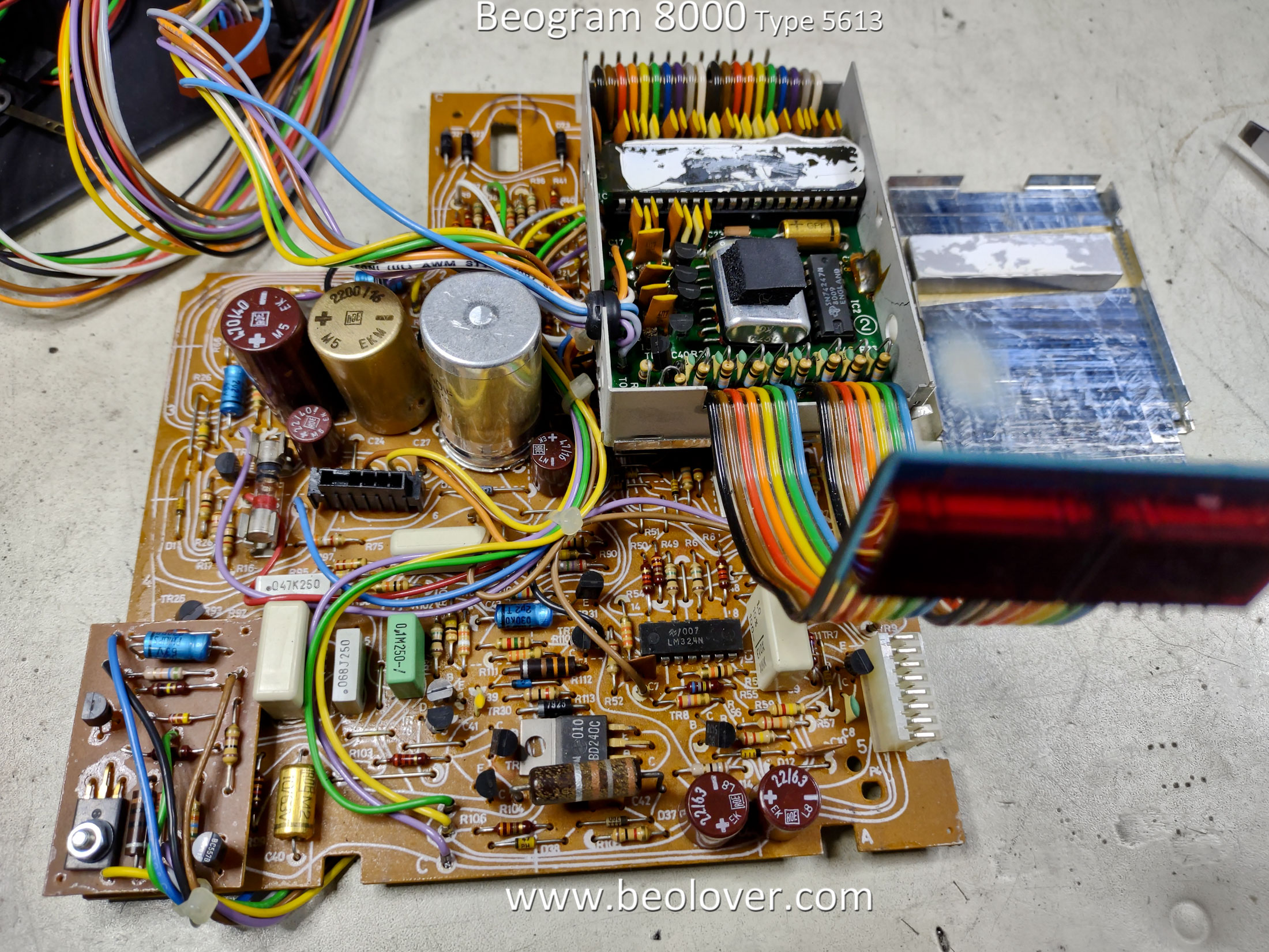
This is the main board again with the uC board attached to it.


The uC board only has one electrolytic capacitor to replace but it is important as it is for the +5 VDC power to the uC. 

This model Beogram 8000 is an early serial number unit and does not have the additional daughter board inside the uC compartment.  Without that board it is easier to see the 10uF capacitor that needs replacing.

On the main board the large 2200 uF capacitor has a three-prong base to secure it to the circuit board.
I like to remove and re-use that metal base for the replacement capacitor.


The rest of the capacitors are just replacement of the two wires on each capacitor.
On these boards I replace electrolytic capacitors that are 4.7 uF and smaller with WIMA MKS non-polarized capacitors.

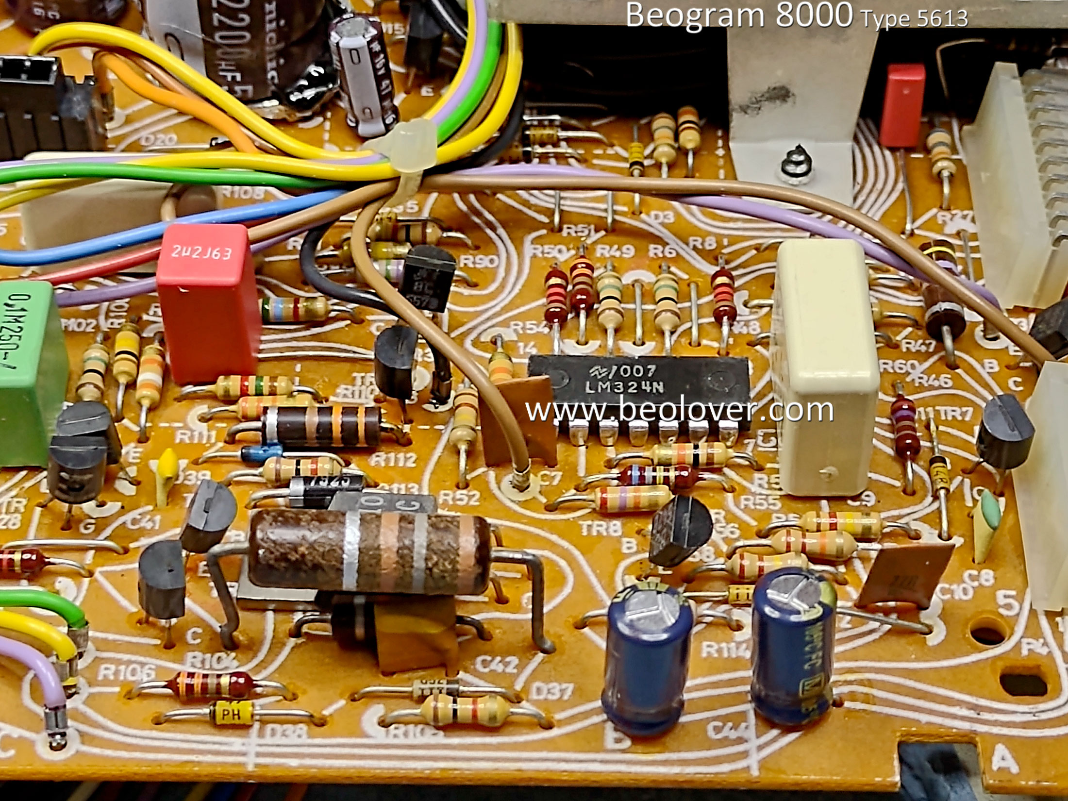
Here are photos of the main board after the capacitors have been replaced.


Here is the lone floating chassis electrolytic capacitor that was replaced.  A 10uF, 63 V capacitor on the +5 VDC regulator.  Later models changed this (0C2) capacitor to 47 uF and the 0.22 uF (0C1) capacitor to a 1 uF capacitor.  That is what is shown in the Beogram 8000 service manual.  

In this case I am keeping the values that this model came with.


On the 4C1 capacitor inside the transformer box the original 27 uF, bi-polar capacitor measures out of tolerance.


I haven't been able to find a good 27 uF, bi-polar replacement capacitor so I have created a couple of options for the replacement.  

I can use two 56uF polarized capacitors in series, configured with their negative leads soldered together.
Or I can use two bi-polar capacitors in parallel that add up to 27 uF.  Of course the capacitors must be rated for at least 55 V.  I used 63 V rated capacitors.


I went with the two bi-polar capacitors in parallel as they produced a value of just over 26 uF.


Another bit of electrical work was to replace the phono signal muting relay where the phono cable connects to the Beogram 8000.  To mute the audio signal when the tonearm is raised the B&O engineers used a relay to ground the left and right phono signals...muting them.


With all of the electrical work completed it was time to clean the tangential arm transport, re-lubricate it and change the servo drive belt.

This sequence of photos begins the work by removing the servo belt since the belt needs to be removed in order to remove the drive spindle and rails.


Next, I removed the drive spindle and rails from the tangential arm assembly for cleaning and re-lubricating.

The spindle is not too dirty.  There is some old white grease that is a little dry.  The dark grease is the mixture of original oil and grease that B&O used for the turntable spindles (since the Beogram 4000).
It is part Mobil NUTO H32 oil and part Rocol MTS 1000 grease.


I disassembled the spindle fully and examined the plastic spindle nut.  I have come across a few Beogram 8000 units where one side of the nut is badly worn.  This one is perfect though so that is great.
I cleaned off all of the old grease before applying fresh grease.


I made up a fresh mixture of NUTO H32 oil with some Rocol MTS 2000 grease.  I have never been able to find MTS 1000 grease but an technical representative for Rocol that I contacted told me that MTS 2000 is essentially the same product...but a heavier duty version.  In either case it has to be mixed with NUTO H32 oil so that it is diluted to an oily consistency.


After brushing it onto the spindle I re-install the spindle nut.

For the two shiny rails that the tangential arm assembly rides on I apply a coating of Molykote DX paste.


While the spindle and rails are removed it is a good time to check and make any adjustments needed for the height of the tonearm when it is at rest.

The top surface of the tonearm should be even with the top surface of the fixed arm assembly.
The adjustment screw for the tonearm height is located underneath the tangential arm assembly which makes is inaccessible when the tangential arm assembly is in its normal position. With the sled assembly disassembled right now, the adjustment screw can be easily accessed.

In the photo I highlight a plastic strip that I add.  I epoxy it in place.  Frequently a Beogram 800x turntable can develop a problem where the arm lowering function is a sudden drop instead of a slow, controlled lowering process.

The reason is usually because the tonearm height adjustment screw is touching the metal, underneath side of the tonearm (the counterweight).  That connection begins to stick and there is a delay in the lowering of the tonearm.

Adding the plastic strip prevents the adjustment screw from directly touching the metal base.


The arm lowering mechanism should also be checked at this time for any obstructions.

Now the spindle and guide rails can be re-attached to the tangential arm assembly.

The black, plastic holder that slides along the back rail and fits over the slots in the spindle nut must be lined up and fitted while the tangential arm assembly is turned over (as in the above photo).
Also note the black plastic post in the above photo just to the left of the arm lowering/raising mechanism.  The black, plastic holder must be fitted to that post.

As the spindle turns the spindle nut travels along the spindle threads.  The sled spindle holder moves along with the nut and pulls the sled with it (via the mounting post).


The tangential arm assembly sled is carefully turned back to right side up as the spindle and guide rails are fit into their respective positions.

I use some Tri-Flow Red Grease for the mounting points of the spindle.


This photo shows the new servo drive pulley next to the old one.  


The tangential arm assembly is now back in place.  The Beogram 8000 is almost ready to be hooked up and some initial tests run.


I still had to fix the problem with the Beogram 8000 button panel.
The original frame for the button panel has a bunch of broken mounting tabs.  More broken ones than intact ones actually.

The best solution here is to use one of my spares.


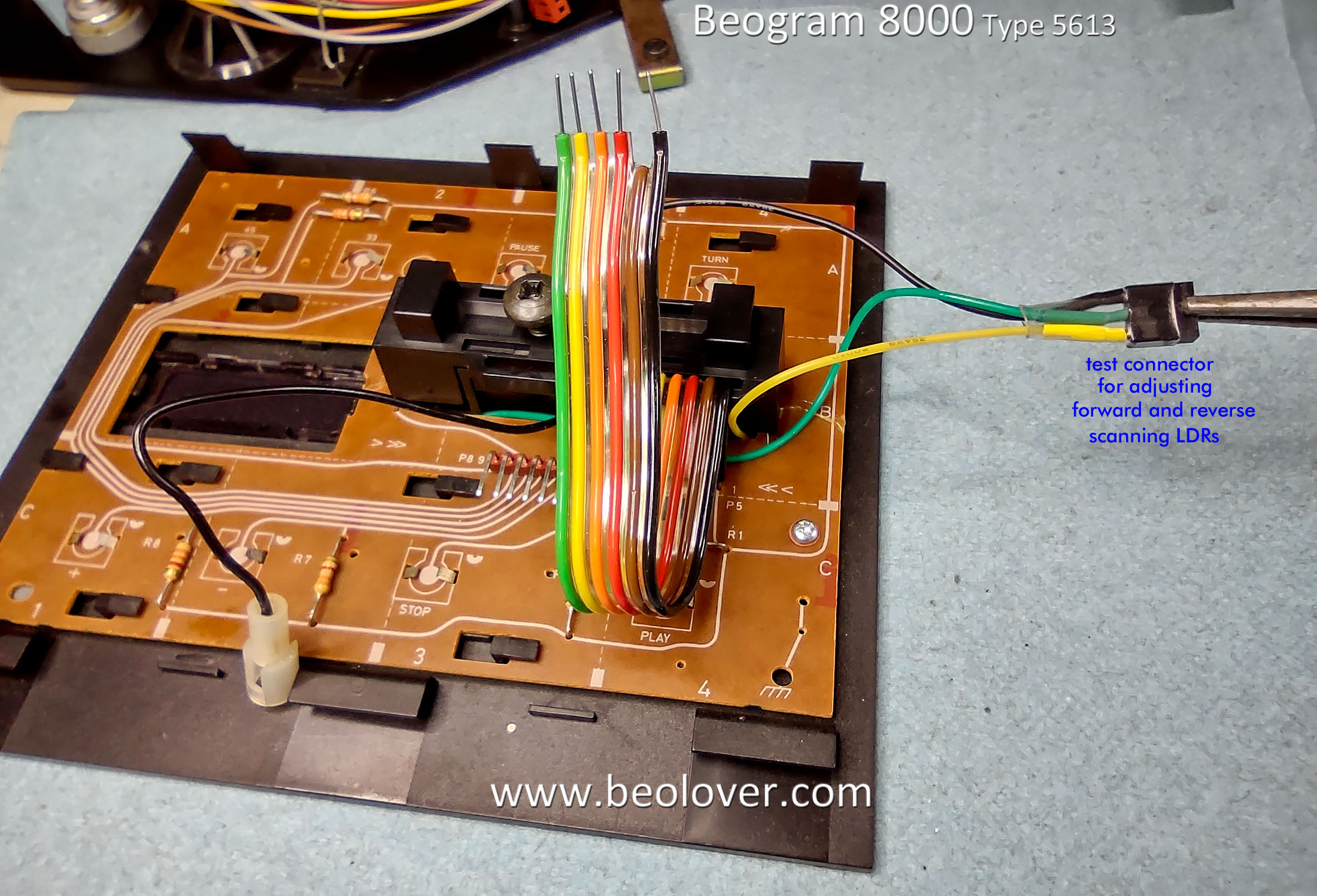
Another task I always do when working with the button panel is to add a test connector for the forward and reverse scanning LDR devices.  The black, plastic housing on the button panel houses a lamp and two LDR devices.  The two black screws adjust the light on each LDR.  The service manual describes the adjustment procedure to set the voltage on the LDR test points where the steady-state voltage measures 620 millivolts to ground. The actual range is pretty tolerant so I typically try to set the voltage to around 650 millivolts.

The problem with this adjustment is the adjustment screws can be difficult to turn and you have to hold the board securely while trying to keep leads on the test points.  Also, there are no convenient test points that allow this check to be made when the Beogram 8000 is re-assembled and no longer in the service position.  I wanted a way where I could just open the button panel, without putting the Beogram into the service position, and make the adjustment.

Note: If you find it difficult or impossible to achieve the service manual adjustment value then it is likely the LDR devices, sensor lamp, or both have failed and they will have to be replaced.

I add this test connector to all of the Beogram 800x turntables I work on.


Now this Beogram 8000 can finally be checked to see how the electronic restoration work went.

Connecting the transformer, PCBs 1 & 2, button panel, floating chassis connectors and tangential drive rotor together are all you need to check out if a Beogram 8000 is functioning.

Warning: If you do not install the rotor for the Beogram 800x turntable while attempting to test it you can damage the circuit board (unless you keep connector 1P4 disconnected).

Here is the Beogram 8000 plugged back into power for the first time since I started the restoration.
The expected Standby red dot is a welcome sight.


A quick press of the Turn button (to test of the speed regulation) showed that the speed sensor works and the Beogram uC can lock in 33.33 RPM.


Operation during Play however, did not result in proper operation.
The fixed arm, red LED (at the end of the arm) did not illuminate during scanning mode.  The LED should light up during scanning.


Another problem was the fixed arm record detection was not working.  The fixed arm sensor wasn't reporting an empty platter.

I had to disassemble the fixed arm sensor/lamp assembly to investigate the problem.

Here is the schematic diagram of the Fixed Arm wiring for this early serial number, Beogram 8000.


As you can see, there is one incandescent lamp, one LED and one sensor in the Detector Arm.
The LED only illuminates the red dot at the end of the fixed arm.  The "<" and ">" areas of the arm cover are not used (even though the markings are there).

Here is the fixed arm detector circuit board.  Note the wire colors in reference to the color codes I list on the schematic diagram.


It turned out that the fixed arm, red LED had failed.  In addition, the fixed arm sensor had a loose wire.

Here is the fixed arm sensor assembly removed and disassembled (along with a spare to show both sides of the little wiring board).


I found a suitable replacement LED.  It isn't something that typically fails so it being failed is kind of odd I think.

The original LED was painted black to limit the emitting light to just the tip that fits through the hole in the front of the Beomaster fixed arm.

I did the same and painted the replacement LED which, of course, meant allowing some drying time.

When I reassembled the fixed arm sensor I used some magnet wire for several signals as it eliminated the possibility of accidentally shorting out signals. The wire routing looks a little cleaner now.


A quick test showed success of the fixed arm sensor assembly rebuild.
The scanning indicator LED functions now and the record detection circuit now recognizes an empty platter.


I need to finish up the service manual checks and measure the key power supply voltages while the Beogram is open.

I also need to finish rebuilding the Beogram 8000 cabinet.
This Beogram had the usual loose cabinet pieces from the old, original double-sided tape deterioration.
However, it also had a bit of damage from the dust cover being mishandled.

I have been able to repair the broken hinge pieces of the dust cover with epoxy and I have removed all of the old double-sided tape residue.

Here are some summary photos of that process.
These first few photos show the GooGone process of loosening the old tape residue for removal.


Here are the pieces with the residue removed.


Finally, here is the dust cover damping mechanism hinge all cleaned up, ready for epoxying in place.


The next post will be a fully tested Beogram 8000.  Ready to use.