Featured Post

Beolover SyncDrive: DC Platter Motor Replacement for Beogram 4002 and 4004 (Type 551x and 552x)

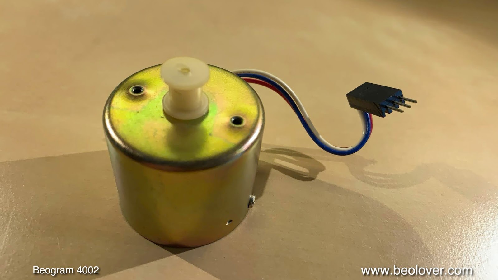
Late Beogram 4002 and the 4004 (Types 551x and 552x), which have DC platter motors instead of the earlier synchronous AC motors usually suff...

Monday, August 24, 2020

Update of MMC Cartridge Box for MMC 1-5 Cartridges

A while ago I designed a storage and shipping container for MMC cartridges. Initially this container was only outfitted with an insert for the old style MMC20 cartridges.

I just designed a new insert specially designed to hold and protect the newer MMC1-5 cartridges:
It opens like a book. Just stick the cartridge in the specially molded holder:
The inserts are printed from flex filament, i.e. are a bit elastic for a gentle and safe fit of the cartridges.
That is how they look closed. A little window shows what is inside:
Beolovely! Like all our parts these boxes are available to other enthusiasts!


Tuesday, August 18, 2020

Beogram 4002 DC Platter Motor Restoration

I recently received a Beogram 4002 DC platter motor from Idaho in need of restoration. This shows the motor:
I disassemble the motor to extract the bearings for oil infusion:
The bearings are the two small donuts on the pad up front. I immersed them in motor oil and pulled a vacuum:
Immediately, vigorous bubbling began indicating that air was drawn from the porous Oilite material to make room for oil inter-diffusion.
After about 3 days the bubbling stopped and it was time to extract the bearings from the oil:
I reassembled the motor and installed it in one of my Beogram 4002s for testing with the BeoloverRPM device, that allows logging the RPM in 10s intervals for extended periods of time:
After about 24 hrs I had measured this curve:
This is a pretty good result for a Beogram DC platter motor, i.e. this motor is ready for duty again!


Saturday, August 15, 2020

Beogram 4004: Repair of Seized Platter Motor and Its Drive Circuit, and a Few Adjustments to Get it Going Again

Recently I received a Beogram 4004 from the UK for repair. The unit did not drive the platter anymore. I The first step was to extract the DC platter motor for restoration:

I tried to run it with my bench supply, but the rotor would not turn. In fact I was not even able to turn it by hand. It was completely seized. I pulled the pulley off and extracted the motor from its outer housing. Then I put a drop of WD40 on the shaft where it meets the top bearing and let it sit for a while. After the WD40 had done its job, I was able to move the shaft and extract the rotor from the housing when I took the motor apart. This shows the disassembled motor with the bearings extracted for oil infusion:


I submerged the bearings in motor oil and pulled a vacuum:

Immediately, vigorous bubbling started indicating that the vacuum drew the air from the empty pores of the Oilite bearing material. This created room for oil to replenish the bearing. After about 72 hrs the process finally stopped and it was time to extract the bearings:
I reassembled the motor and put it back into the Beogram 4004 for testing. I pressed start: And nothing happened! The motor did not turn. Since it ran nicely from the bench supply, there had to be something wrong with the motor drive circuit. I checked the voltage at the emitter of 1TR2, and it was zero. Normally it should be about 8-9V. TR2 supplies the motor circuit with a stabilized current, but not now. This suggested that TR2 had a problem. I extracted it and checked it with a transistor tester:
The transistor tester saw it as a diode, i.e. one of the junctions was open circuit. I replaced it with a TIP120 transistor which is a bit stronger (5A) than the original TIP31 3A transistor. Using another TIP was also convenient to maintain the same package layout, so it would fit into the same spot on the circuit board (it's heatsink is soldered to the board with a feedthrough plug). My theory is that this transistor died due to the seized motor drawing maximum current for a while at some point.
After installing the TIP120 the motor started running and I moved on to replace the RPM relay and the RPM trimmers, frequent sources of RPM instabilities in DC motor Beograms. This shows the original setup of the RPM section of the PCB:
And after installing the new relay and trimmers:
After this I installed the board again, and checked the sensor signal to make sure the record detection mechanism was up to snuff:
This signal looked good, so it was time to measure the RPM stability over a 24 hrs period with the BeoloverRPM device:


The BeoloverRPM allows recording the RPM for extended periods of time in 10s intervals. This is the curve I measured:

This measurement is as good as it gets with Beogram DC platter motors.

My next focus was the arm lowering mechanism, which was sluggish. This was apparent when I played a record and the needle dragged over the platter when the carriage returned. This usually indicates that the lubricants are hardened and that the mechanism needs to be taken apart for cleaning and lubrication. This shows the mechanism:
I disassembled it
and cleaned everything in an ultrasonic bath. Then I put everything back together and the the arm lowered and raised smoothly again.
Now it was time to adjust the tracking weight. It turned to that the adjustment mechanism was seized. I was not able to turn the adjustment wheel at all. I took it off and it turned out that the secondary pinion was stuck in its orifice in the arm base:
I put a drop of oil on the shaft and then it started moving again. I put the adjustment wheel back on and calibrated the counterweight to make the scale accurate between 1 and 1.2g which is the range that counts for B&O cartridges:
Then I adjusted the arm lowering limit to prevent future damage to a cartridge, and then it was time to play a record. It performed admirably and if it can repeat the task a few more times it will be time to send this Beogram back to the UK.


Monday, August 10, 2020

Beogram 4000: Replacement of an 'Old Style' MMC Cartridge Mount with a New 3D Printed Assembly

The Beogram 4000 that I am currently restoring also had a cracked MMC cartridge mount. Unfortunately, this is a problem common in many Beogram 4000 since the plastic B&O used for the cartridge mount seems to get brittle as it ages. Later Beogram 4002 and 4004 have cartridge mounts made from a different plastic, and it rarely happens that they break.

The first step was to remove the tone arm to be able to push the plastic assembly out of the arm from the back. Later 4000s have a mount that is glued in and one can remove it by 'cooking' the arm for a while in boiling water to soften the glue until one can push the mount out. More details about this procedure is posted in this blog post.

This post is about doing this replacement for an 'old style' arm, where the mount assembly is bolted into the aluminum profile of the arm. This shows the back end of the arms. The tone arm up front can be removed by taking out the screw that holds the aluminum profile to the arm base:

Then the arm can be pulled out:
Do this carefully, since there is a little spring on the excenter that allows adjusting the arm forward and backward (there is a small plate on it, that has already been removed in the above picture, but is shown in the 2nd picture below under the arm). 
Once the arm is off a small PCB is revealed that makes contact to the MMC mount assembly in the front end of the arm:
Turn the arm around, and the screw that holds the cartridge mount assembly in place can be accessed:
I removed the screw, and then carefully pushed the plastic assembly out from the back of the arm using a 8 mm diameter rod with a smooth end (to not damage the back end of the assembly) that fit into the aluminum profile. The extracted parts are shown in the upper part of the picture below:
The assembly consists of three components: (1) A 'carrier' that also has the tab (broken off) onto which the cartridge is stuck. The tab end of the carrier carries the flex circuit board that has the four traces for making contact to the coils of the cartridge (it came off due to the broken of tab). (2) A separate part that carries a grounding tab to make contact to the metal body of the cartridge, and (3) a part in the back that makes the connection to the PCB reaching into the back of the arm.
Below the extracted parts, the new plastic parts that I designed for this repair are shown. They were printed at Shapeways in black PA12 plastic, which is a sturdy engineering plastic that has a bit of flexibility while also being pretty stiff. Perfect for a cartridge mounting tab that is not supposed to break off when it is torqued a bit.

Since in this case also the grounding tab was damaged, 
I needed to design a replacement for this component, too.
The challenge was to find a suitable metal strip for fashioning a suitable grounding tab. After a bit of head scratching I had the idea to use an 'ammo pack' strip from Molex-style connector terminals:
I removed the terminals and plated the ammo strip with nickel and then with gold. Then I cut a small part off and bolted it into the 3D printed plastic part and bent the end into a suitable tab shape:
The next step was to glue a new flex PCB strip with the coil contacts (also Ni/Au plated) into the business end of the carrier part:
Then it was time to transfer the wiring:
After the soldering was done (use a small tip and be quick not to damage the plastic parts), the insert could be assembled together with the original back end part:
For assembling the ground tab part with the carrier, it is a good idea to stick a cartridge on it, which allows aligning the ground tab part with the back plate of the cartridge. I fixed the ground tab part in place with a dab of super glue gel on either side. The back end was glued on with contact cement (like in the original assembly).
And now came the interesting moment! Would this new assembly line up with screw hole in the arm tube when inserted into the tube?
Luckily it did:
While the cartridge sat snug on the end of the aluminum profile without a gap:
Perfect! This spared me another design iteration to make things match. It rarely happens that a part like this really fits on first attempt, but this time I was lucky! This shows the new cartridge mount with removed cartridge:
Beolovely! 

Time to put the arm back into its place:
A few more adjustments and it will be time to give this Beogram 4000 a first spin!


Friday, July 31, 2020

Beogram 4002 Type 5513: Return to the workbench for a new phono cartridge mount - Conclusion

The new Beolover replacement phono cartridge mount is installed now in this Beogram 4002 Type 5513 turntable.

This type of restoration is always fun. My very first collaboration with Beolover was on one of my Beogram 4000 turntables where we decided there needed to be a replacement phono connector so the repair didn't have to use a donor Beogram. Since Beolover created this phono connector part it has saved many a Beogram turntable I am sure.

Certainly this Beogram 4002 Type 5513.

Here are the components again -


I like to replace the phono wires on this type of repair. I use color coded 36 awg wires.


Preparation for the repair means tinning the leads of the new wires and the connector assembly contacts.


I start with the two inside wires and finish with the outside wires.


Note that the bottom part of the Beogram phono connector assembly reuses the original connector part.

Before I join the two halves of the phono connector I use a some Aleene's Tacky glue to hold the wires in place and act as kind of a strain relief while I work on the repair.


This is why you keep old MMC phono cartridges...even if the the cantilever and stylus are gone.
They are perfect for this repair in making sure the phono cartridge assembly is put together correctly and inserted just right into the tone arm. Aleene's Tacky glue is used again on the joining of the two phono connector halves.

I also use a little more of the Aleene's Tacky glue inside the tonearm when I reinsert the phono connector assembly.  That insures the phono connector is secure but it could still be taken out again in the future. You don't want to use something permanent like epoxy here.


Now I just had to connect the phono wires to the signal transfer board and this repair will be done.


That concludes the Beogram 4002 Type 5513 phono cartridge connector repair.

Because this repair required so much handling of the tonearm I will have to go through all of the service manual tonearm adjustments again to make sure this Beogram is ready for use again.

Hopefully most of the components will still be adjusted correctly but they still have to be checked.

Monday, July 27, 2020

Beogram 4000: A Fun Time with a Suddenly Activating Solenoid, an Anemic Carriage Motor, and an AC Motor Driver with a Weak Driver Amplitude

I am making good progress with the Beogram 4000 that I recently started to restore. More about the standard restoration tasks in a following post. This post focuses on two non-standard issues with this Beogram that I encountered after rebuilding its boards and motors.

I started realizing there was something wrong when I adjusted the platter height relative to the arms. During this process I needed to drive the carriage, so I plugged the Beogram in and I realized that the carriage movement was a bit slow compared to other 4000s I had worked on previously. I measured the 24V rail, and it only showed 21V. A bit odd. Usually this is 25-26V due to a warm Schottky diode, or 23.8V in my case since I now always replace the original 1.3W diodes with a cool running modern 5W type, which brings the voltage down to 23.8V at the capacitor terminal. But in any way the presented voltage was way too low.
Then I accidentally touched the carriage in a way that it was lifted up in the back a bit. This briefly activated the arm lowering solenoid. Very strange!!
I was able to reproduce this and it dawned on me that there must be a major issue, somehow putting a significant voltage onto the carriage when it touches the floating chassis (the carriage is normally insulated due to the plastic components that hold it on the guiding rods. The solenoid issue even 'worked' with the Beogram turned off (but plugged in).

I put the multimeter to it, and after poking around for a while, I realized that the enclosure of the Beogram was at ~30V relative to the system ground. Not a good sign, I counted myself lucky that there had not already been some 'magic smoke' emitted from an unlucky component. I also realized at this point that the transformer got unnaturally warm. 
30V 'smelled' like the unwanted voltage originated from the 24V system, which is fed by about that voltage before the Schottky diode (OD2)/transistor (TR1) regulator stabilizes it to ~24V. 
I determined that there was a ~9 Ohm short between the positive end of the 24V 3000uF reservoir cap (0C4) and ground:
More precisely, the short was between the red lead connected to the cap and the chassis. I followed the red lead, which goes to the collector of 0TR1. So first I suspected 0TR1 might have an issue, but it turned out to be o.k..
But at the collector of the chassis-mounted 0TR1, the red wire from the cap meets a thin blue wire, which goes straight to the carriage circuit board, and from there to the right contact of the solenoid, supplying it with un-stabilized 30V for maximum action! The plot thickened. I successively unsoldered/measured/re-soldered all the connections as I 'moved away' from the collector of 0TR1 keeping an eye on the resistance to the chassis. I made it to the left solenoid contact, and then to the terminal where the solenoid connects to the collector of its driver, 0TR4. All the while the short remained, i.e. all that separated me from the chassis was now 0TR4. A closer look at 0TR4 revealed that previous 'creative human interaction' had caused the bolt insulator to go AWOL:
The way this transistor is bolted down, a direct short is made between its heat sink (=collector) and the chassis via the bolt. What was missing is a part like this, which I fortunately had in my stash:
I installed it
and this cured the spontaneous solenoid activation issue. Details, details!!...;-)

I measured the 24V rail again, but the voltage was still only at ~21V and the carriage still moved too slow. So there had to be a secondary issue draining power from the system. Also the transformer still ran pretty hot. The other 'power electronics' system of the Beogram 4000 is the AC platter motor. So I measured the AC platter motor signal just to make sure this was working properly. What I saw was a much too low signal, however:
The RMS voltage was only 2.5V with the motor pot adjusted to the maximum smooth waveform. It should be about 5.5-7V when everything is up to specs. This suggested the secondary issue was in the motor driver. I moved the main PCB out of the way and had a look at the push-pull output stage of the motor oscillator beneath it:
The left transistor is 0TR2 (NPN, push) and the right is 0TR3 (PNP, pull). Since the motor wave was about 50% of normal, I immediately suspected one of them being in trouble, causing the motor to run only on one 'cylinder' instead of two. I touched the transistors and I found the PNP to be pretty hot. I extracted it and measured it with my transistor tester, and it appeared to be in perfect working order. So it had to be the other one! I extracted it, too, and indeed, it had turned into a small resistor:
This basically caused the NPN transistor to carry a big DC component along with the AC fed to the motor, explaining the high heat load.
I replaced 0TR2 with a BD437G power transistor (45V, 4A - a bit stronger than the 3A original TIP32),
(this modern package does not need a bolt insulator since the heat sink is encased by plastic on all its bolt facing surfaces)
and that cooled down things while yielding a normal strong motor signal for 33 RPM
and 45 RPM:
After this the 24V rail also was fully restored to 23.8V, and the carriage now moved much more quickly. 
On to do the final adjustments and giving this baby its first restored spin!

UPDATE: 

My customer suggested: "You write that 0TR3 (PNP, pull) was hot but working.  Running transistors hot obviously shortens their lives and I’m just wondering, now that you know this circuit had a problem, would it be worthwhile to just replace 0TR3 pro-actively to make sure that there isn’t a latent issue that could lead to another failure downstream?"

I thought that made a lot of sense!...;-), and so I put in the complementary PNP (BD437) in, too:
If you do this at home, note that the BD437/438 SOT-32 packages have base and emitter reversed compared to the original TIP31/32 TO-220 types, i.e. the brown and blue/orange wires need to be reversed.