I am working my way through a stack of Beogram 400x and I just completed this Type 5503 Beogram 4002 unit from California, which is a 2nd generation AC platter motor design for 110V grid voltage, that has already the optical carriage position detection system that one finds in the latter DC motor types (551x and 552x). Please, refer to my initial post about my assessment of this unit before the restoration. If you are interested in any of the parts that I used in this restoration, they are all available to other enthusiasts. Just send me an email or use the contact form to the right.
The first step of any Beogram 400x restoration is always the cleaning and re-lubrication of the arm lowering mechanism since the old lubricants are often hardened, impeding the arm movement.

I took the mechanism apart

and cleaned everything. I usually lubricate the damper with a bit of motor oil, and the pivot points with a synthetic grease.
Then I moved on to the damper to tonearm linkage, which is also often stuck:

This requires the removal of the sensor arm. After reassembling (make sure you do not loose the small spring that sits under the circlip that holds the linkage on its pivot shaft) it was time to adjust the arms orthogonal to the carriage and parallel to each other:

I continued the restoration of the carriage/arm mechanism with the installation of a new tracking sensor light source based on a 3D printed housing with an LED and a brightness adjusting trimmer:

Installed:

The final step of this part of the carriage mechanism restoration was cleaning the spindle and re-lubricating it, and replacing the old cracked pulley with a new precision machined aluminum unit (I get them from an enthusiast in Vienna, please, send email for contact info if you need one):

On to rebuilding the electronics. I replaced all capacitors

and installed new 25 turn RPM adjustment trimmers

and I updated the record detection circuit with a new high-gain transistor and a 5MOhm trimmer for precise adjustment of the working point of the amplifying transistor:

From the solder side:

I adjusted the working point of the transistor to the prescribed 4V:

After this I replaced the reservoir and motor phase capacitors

with a 3D printed assembly that holds the modern, much smaller capacitors neatly in place:

After this a preliminary test with the platter installed revealed a knocking AC motor. I extracted it and took it apart to do an oil infusion of the bearings:
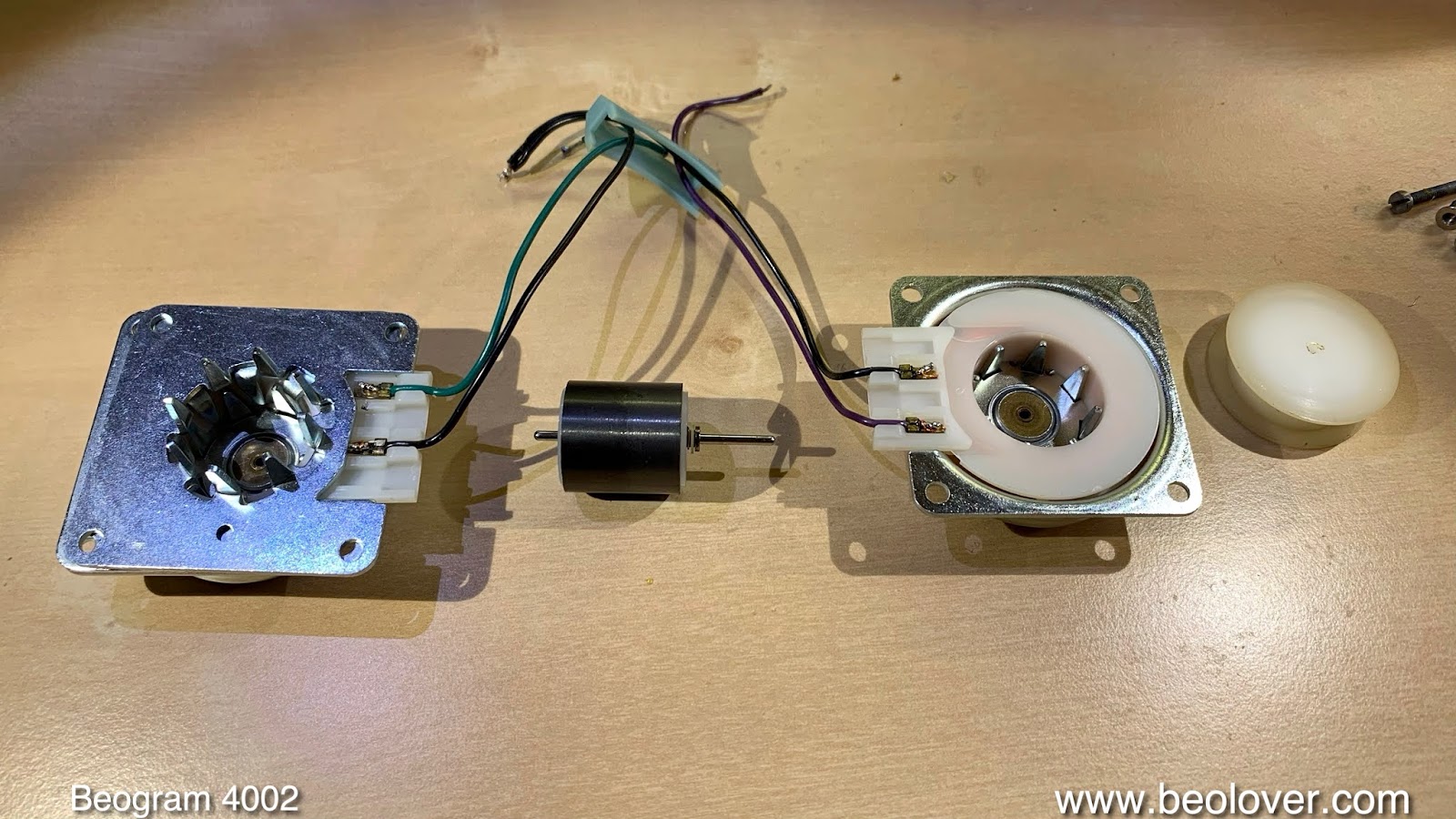
The bearings cannot easily be extracted from the can-halves and so I usually immerse the entire housing in oil:

After a day of immersion I put everything back together and re-installed the motor.
I took the keypad out and removed the output PCB to replace the output relay with a new encapsulated unit and to replace the capacitor that controls the relay delay. I also installed a switch with which one can connect the system and signal grounds if desired. Often, when there is humming, connecting the grounds cures the issue.

The next step was to install LED light sources in the RPM panel. The original incandescent bulbs can have an adverse effect on the RPM stability due to the temperature change they impart on the user adjustable RPM trimmers in this panel. This shows the LED replacements:

They are a drop in replacement for the light bulbs:

After testing the LEDs it turned out that the 33 RPM trimmer indicator had a wavy white reflective background:

This is also a result of the heat load the original bulbs put into this assembly. I tool the panel apart. This shows the wavy background sticker.

I replaced it with a cut to size piece of white insulating tape:

and put the assembly back together:

Beautiful...no more waviness!
On to replacing the last light bulb, the one in the sensor arm. This shows the original bulb installed together with the flex-PCB based Beolover LED replacement circuit:

This part is based on a warm-white LED and a pass-by resistor that simulates the presence of the original light bulb (necessary due to the low power consumption of the LED).
This shows the installed component:

And in action:

These LEDs emit enough red photons to make the B&O logo show up in its warm red-orange color.
The next step was to replace the deteriorated transport lock bushings. This shows the new replacement bushings:

They consist of two halves that can be inserted into the mounting holes from below

and the top:

After this the locks can be reinstalled. Then I replaced the cracked cabinet guiding washers with 3D printed replicas. The black one is for front-center, preventing visibility through the gap between plinth and aluminum panel:

This shows one of the washers installed:

After this it was time to improve the tonearm counterweight mechanism by installing a M3 nut on the adjustment screw to replace the locking washer. The nut enables locking the weight position in place for posterity, greatly enhancing the stability of the weight calibration:

After positioning the counterweight I calibrated the scale and adjusted the tracking weight to 1.2g, which is appropriate for most cartridges that can be used on the 4002:

After this procedure, I adjusted the arm lowering limit:

This is important should the record detection mechanism ever fail. It makes sure that the needle misses the black ribs on the platter if there is no record.
The final adjustment was the tracking feedback, a process which is facilitated by the intensity adjust trimmer on the sensor light source:

Now it was time to test the RPM stability of the platter motor. I hooked up my BeoloverRPM device and ran it for about 24 hrs. This is the curve I measured:

An excellent result as one can expect from the AC motor Beograms. While the rapid fluctuations are pretty much similar to what the DC motors achieve, the longterm stability over several hours is better. Not that one would be able to hear the difference, these are very small fluctuations, but still, the AC motor is generally the better choice. Here we see the advantage of not having a temperature sensitive feedback system controlling the speed. Instead a strong (that is the main reason why the AC types are power hogs compared to the DC motor models) AC motor follows a stable voltage oscillation, and that keeps the speed very constant over time.
After the RPM test it was finally time for a test drive. I selected a CTI album that I recently discovered, "Concierto" by the guitarist Jim Hall (CTI 6060). His version of Concierto de Aranjuez is rapidly becoming one of my favorite record sides:

This record was of course ultrasonically cleaned with the Beolover's CleanerVinyl Pro System before it was played on this lovely Beogram 4002.
I will now play this Beogram for a couple weeks to make sure that there are no intermittent issues, and then it will be time to send it back to its owner.


