Featured Post

Beolover SyncDrive: DC Platter Motor Replacement for Beogram 4002 and 4004 (Type 551x and 552x)

Late Beogram 4002 and the 4004 (Types 551x and 552x), which have DC platter motors instead of the earlier synchronous AC motors usually suff...

Monday, December 19, 2016

Beogram 8002: Mechanical Adjustments and a Scraping Sub-Platter

After bringing the electronics up to spec it was time to put this Beogram 8002 also mechanically back to perfect functionality. I usually clean the carriage mechanism and re-lubricate everything, replace the carriage drive belt and adjust the tonearm parallelism. This Beogram also had the 'scraping subplatter issue' that seems to be fairly common.

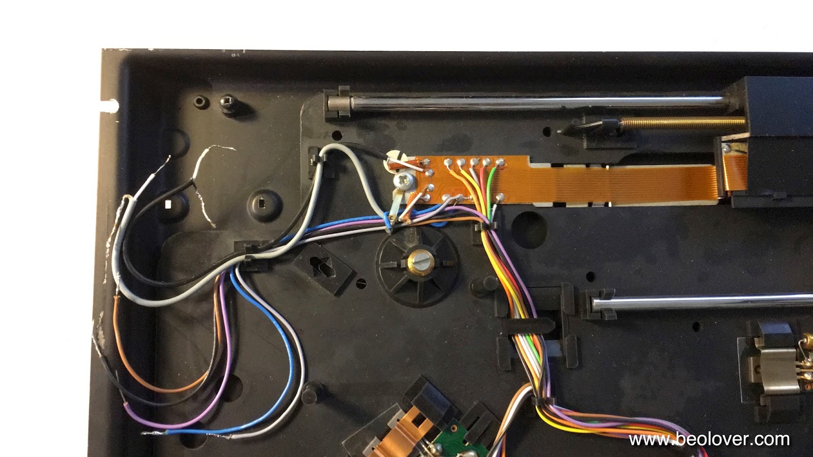
Let's start with the carriage mechanism. This shows it taken apart.
After cleaning off the old grease and replacing it with a modern synthetic grease it was time to adjust the arm, which was pointing upward:
This is the situation after the adjustment:
On to the scraping sub-platter. This is caused by a compressed plastic disc at the bottom of the main bearing that holds the weight of the platter. This disk can suffer during transport if the platter is not taken out. To get to the disk the spindle needs to be take out:
This is done by loosening the screw in the silvery clamp on the right and rotating the arm that holds the sensor assembly that reads out the tacho disk clockwise:
The main bearing is in the center of the photo. This shows the plastic disc pushed up via the small hole in the bottom of the bearing that can be accessed from the underside of the enclosure:
The small orange disk on the right is a 3D printed part that I developed to shim up the white disk by ~0.5 mm. This elevates the sub-platter a bit and the scraping stops. It can be inserted under the white disk without having to take it out. Just flip it vertical with the small rod or similar that is used to push it up and insert the orange disc, then put everything horizontal again with fine tweezers. 
After this operation the platter ran smoothly again. On to installing the "liberated" aluminum plates and the putting the hood back on.


Sunday, December 18, 2016

Beogram 8002: Repair of a Dead Display Digit

Another issue plaguing the Beogram 8002 that I am finishing up right now was that the fourth digit of the RPM display was dead. This shows the sorry state of affairs before my repair:

Since all segments of this digit were not working the most likely root cause of the issue was a missing strobe signal for this digit. A measurement with my oscilloscope at the strobe pin (14) on the display confirmed this hypothesis. Time to 'follow the signal', which is not the most straight forward thing to do in this setup since the unit must be running to do the measurements. I installed some micro-grabber leads in the microcontroller can at strategically important points and then did the measurements with the board installed. It turned out that the trace that connects processor pin 13 to the base of IC6 (the Darlington that drives digit 4) was interrupted midway (between the solder points of the white and ground leads):
The way this looked suggested that this was probably the result of 'human interaction', and of course one wonders what may have compelled anyone to poke around there with a sharp object causing the trace to come off. Anyway, I reestablished contact with a piece of magnet wire:
and the display digit came to life again:
Time to put the hood back on, do the mechanical adjustments and then do some 'reliability testing' (= listening to some awesome vinyls I recently bought...;-) on this lovely Beogram 8002.


Saturday, December 17, 2016

Beogram 8002: Record Detection Malfunction

The Beogram 8002 that I am restoring right now had issues with the record detection function. When pressing start with no record on the platter it would drive the arm to the start groove position and then lower it onto the platter. And that is of course not acceptable considering the high prices of rebuilt cartridges these days...so I had another look under the hood. Here is the relevant section of my annotated circuit diagram:


When no record is present the photocell PH1 generates an alternating current due to the intensity change caused by the black strips on the platter alternating with reflective sections. This current charges C15. The resistors R65 and 64 are there to allow the capacitor to discharge when the photocell is off. R64 allows to change the time constant of the discharging process. By optimizing R64 the AC amplitude that goes into the base of TR14 can be maximized. TR14 ad TR15 amplify the AC signal which finally charges C19 and a voltage builds up at the base of TR16. TR16 turns on and HH is pulled to ground. HH feeds directly into the microcontroller, which therefore can detect the absence of a record and prevent arm lowering and/or drive the carriage towards the center of the platter in search of vinyl.
I hooked up my oscilloscope to R71/R72 and measured the signal with the sensor arm over the rotating platter. What I saw was a signal similar to the curve shown in the circuit diagram. At the same time I measured HH, which turned out to be somewhat inconsistent, fluctuating between 0.15 and 0.5V. This pointed towards a too small pull at the base of TR16 which would therefore not turn completely on.
I tried to adjust R64, but was not able to produce a larger signal at R71/72. After some head scratching I realized that I had maxed out R64 to obtain the largest possible signal. This was strange since one would expect that R64 would be dimensioned in a way that the maximum signal would be obtained somewhere in the middle of its resistive track. I measured the resistance across R65/64 and I saw only ~3k. This was strange since in the circuit diagram 15k and 20k are parallel, which should yield 8.5k...I removed R64 and it turned out that it was a 4.7k trimmer. I replaced it with a 50k 25 turn trimmer and did the adjustment again. And this time I was able to adjust to a clear maximum (8V) of the RMS voltage at R71/72. It is a good idea to use the RMS voltage of the sawtooth since its maximum will correspond to the maximum current pumped into the the base of TR16. This is the signal I measured after optimizing R64:


The corresponding voltage at HH was now a constant 0.13V.
Pressing start now also resulted in the appropriate response of the turntable: It did not drop the arm anymore but instead drove it all the way across the platter and then back to the home position. So this may be fixed! On to the repairing the missing digit in the RPM display.

Friday, December 9, 2016

Beogram 8002: Transplantation of Output PCB

Finally I had some time again to work on the Beogram 8002 that I recently started to restore. The last two weeks were an 'interesting experience' after Michael Fremer's video appeared on analogplanet.com featuring my CleanerVinyl ultrasonic vinyl cleaning equipment. 

The next step in this project was to transplant the DIN7 output assembly from a parts-Beogram 8002 that I acquired from a crooked audio repair shop in Chicago. This unit is now coming in handy here since the 8002 was missing its DIN7 output cluster:
I always wonder what drives people to do such things, but here we are on our interesting little self-absorbed planet...;-).

I extracted the assembly from the parts 8002:
I decided to update the relay with a modern encapsulated unit while I had everything on the bench. The original Omron G2V-2 relay can easily be replaced with its modern G5V-2 cousin, which has the same footprint:
And here is a photo of the installed new relay:
and with its shield clamped on:
This shows the restored wiring:
After verifying that the relay worked properly I installed a grounding switch that allows to connect signal and system grounds if there is a hum problem:
On to the two other issues that I was able to identify: The deck does not detect the absence of records and happily lowers the arm onto the platter. It also has a missing digit in the RPM display. One step at a time.


Wednesday, November 23, 2016

Beogram 8002: Replacing the Motor Phase Capacitor

Today I finished up the recap of the Beogram 8002 that I am restoring right now. The motor phase capacitor is hidden away in the transformer block:
This large can is a unipolar 27uF capacitor. It can be replaced with two modern back to back 47uF bipolar caps. I designed a 3D printed fixture to hold them neatly in place:
This assembly is available to other enthusiasts. Just send me a message via the contact form to the right.
After this was settled I went on to replace the two remaining power supply capacitors that are directly soldered to the small PCB that uses the enclosure as heat sink:
I soldered two new capacitors in
and that concludes the electrolytic capacitor renewal of this Beogram 8002.


Sunday, November 20, 2016

Beomaster 8000: Input Selector Trouble - Tuner Audio Mixed with Phono or TP1 Inputs

*************************Achtung: There is a follow up to this post. **********************

Oh well...I ran the Beomaster 8000 that I finished up recently for some time in my Beosystem 8000 setup and all was well, but then it developed a strange issue: When switching from FM tuner to Phono the phono signal was audible, but the tuner signal was still there in full strength. So instead of switching from one input source to another the Beomaster decided to mix them together instead! So back to the bench it went!

After I opened it up I discovered that I could provoke the issue by wiggling P82 on the uprocessor board. P82 transmits the microcontroller's wishes to the input switches on the preamp board. So this made immediately sense: The FM input did not get turned off when opening up the Tape 1 or Phono inputs due to an intermittent connection (the audio input switches on the preamp board are basically gates that open and close depending on high/low control signals from the processor).

First I thought it was a plug issue, and I cleaned the contacts a second time and bent the header bins a bit to give everything a bit more mechanical intimacy, but the problem persisted. So I came to the conclusion that the issue must be something more serious, like cracked traces or bad solder joints. This photo shows the original condition of the P82 header from the solder side:


Close optical inspection did not reveal anything abnormal, but I was able to demonstrate that at least Pin 1 had an issue since I was able to 'disconnect' it from the component it is connected with by flexing the board a bit. So I put in a magnet wire jumper and put the board back in. After firing the Beomaster up, well, no change...o.k. I took the board back out and this time I jumpered all five solder points to their next neighbors:


Magnet wire is really very helpful for this type of fix, since the polyurethane coating burns off when heated with the solder iron. This allows to make safe wire connections in tight spaces.

After this fix, the problem seemed to be gone. So I put the Beomaster back together...let's see if it is stable now! I usually test these babies for a few weeks until I send them back to their owners. There are just too many components and interconnections that can develop problems, and often they are intermittent. The only way to make reasonably sure that the experience on the customer end is a happy one is to give them a good testing under normal operation conditions. But I sure hope that this was the last post about this particular Beomaster 8000...;-)!

Beogram 4002 (5513): Restoration of the DC Motor - Oil Infusion of Bearings, and Repair of a Broken Off Brush and a Disconnected Sensing Coil

I recently received a package from the Netherlands containing the DC motor from a Beogram 4002 (5513). This motor tested 'dead' after I took it out of the box, so I opened it up. What I found was a broken off commutator spring, which was taped on with 'electrical tape'
No surprise that it would not turn in this condition...Further inspection yielded that also one of the sensing coils had a broken off lead (when everything is o.k. the coils have about 22 Ohms resistance between the contact terminals):
This disabled the feedback mechanism of the motor, i.e. even with intact brushes it would have spun at about 100 RPM instead of 33.33. 

This shows the motor completely disassembled with bearings taken out:
I set out to repair the damage. Luckily I was able to solder the broken brush
back together:
Then I tacked the broken off part of the coil lead back on:
The next step was to do the oil infusion of the oilite bearings. This shows the bearings the moment I put them under vacuum:
The bubbles indicate escaping air from the porous brass material, which at that moment is also replenished with motor oil. After 24 hrs the bubbling had stopped
indicating that the bearings were full with oil again. Then I put the motor back together:
and gave it a 20 hrs test with my BeoloverRPM device. The picture shows my recently redesigned enclosure, which is more practical to use and also more easily 3D printed:
This is the 20 hrs RPM performance graph that I obtained:
Most of this curve is pretty much within spec (±0.05%), but a few spikes that go to about ±0.1% are visible. Unfortunately, this seems to be pretty standard for many of the DC motors in the 551x/552x type series. It may even be an issue with the analog motor control system itself (which comes in many component variations indicating that B&O themselves were experimenting with getting these motors to run more stable). I am still working on figuring this out, which is tricky due to the intermittent nature of the phenomenon. The good news is that these variations are very small. Research shows that most people can identify pitch variations starting at about 0.7%, i.e. this is well below the detectable threshold, and therefore this Beogram will be able to deliver a satisfying listening experience once this rebuilt motor is back on the job.