Featured Post

Beolover SyncDrive: DC Platter Motor Replacement for Beogram 4002 and 4004 (Type 551x and 552x)

Late Beogram 4002 and the 4004 (Types 551x and 552x), which have DC platter motors instead of the earlier synchronous AC motors usually suff...

Showing posts with label test points. Show all posts

Saturday, July 26, 2025

Michigan Beogram 8002 Restoration: Sensor Measurements

The Beogram 8002 from Michigan is performing very good with its turntable functional tests.

I connected some test leads to the Beogram's position sensors, speed sensor, record detection sensor and the forward servo drive signal (IC2 Pin 7).  Reference Beolover's post on the servo motor check.

Here are my test points on the Beogram 8002 PCB 1 board.


First, the position sensors (1 & 2) along with the IC2 Pin 7 output to the servo motor.

This picture shows the signals when the Beogram 8002 is doing a forward scan over the platter.
The image on the left is of the Fast Forward Scan and the image on the right is the Slow Forward Scan.


I placed a test record on the platter and measured the sensors again while playing a record.

The servo IC2 Pin 7 signal varies as the servo motor advances the tonearm assembly to track the record groove.  It does this once every revolution of the platter.


The tonearm controls worked perfectly and the Beogram 8002 record play was great.

Next I swapped out the test lead on the Position 2 and IC2 Pin 7 test points with the Speed Sensor and Record Detection test points.

The Record Detection on the Beogram 8002 is interesting compared to the Beogram 8000.
The Beogram 8000 platter is very similar to the Beogram 4002/4004 platters so the platter detection in the fixed arm just measures a series of pulses by detecting the platter ribs.

With the Beogram 8002 B&O designed a special laser engraved platter with two different sections of black markings as well as a flat gray section.

Here are the Beogram 8000 and Beogram 8002 platters side by side.


The Beogram 8002 platter design results in a different record detection signal than the Beogram 8000.

Here are photos of the Record Detection sensor measurements and the Platter Speed sensor measurements.  I kept the Position 1 sensor as a reference.

This first set of images is with the platter speed at 33.33 RPM.
I actually set the speed to 33.33 RPM to show the Record Detection sensor at the black marking level and at the gray section level.  The photo on the left shows the Record Detection sensor over the black markings.


Here is he platter speed set to 45 RPM but I only captured the signals over the gray section of the platter.


I am satisfied that this Beogram 8002 is functioning properly now.

I will play a couple of records with the components still removed from the cabinet just to test the sound and make sure the audio mute relay is working.

Then I will do the cabinet repairs and reassemble the Beogram 8002 to complete the project.

Friday, July 1, 2022

Beogram 4004 Type 5526: Control Signal and Sensor Signal Measurements

In this post I will show some bench measurements of this Beogram 4004.
It has been performing great and it is time to look at what is going on electronically (since I completed all of the electrical work).

I used an oscilloscope to monitor four key control signals.  Then I measured the Run-Off Stop circuit signal from the position sensor.  Last, I measured what the record detection sensor circuit looks like as measured at transistor 1TR3.  

Here is the relative part of the schematic that shows the four control test points I measured.
I wanted to capture those test points for various key Beogram control events (i.e. Start, Stop, Cueing, etc.).


Highlighted on the diagram are four control signal test points (ON, OFF, Cue Down and Cue Up).

Note: B&O changed the wording on the Beogram 4002/4004 control buttons so in some Types there are buttons: ON (<<) and OFF (>>) while on other Types the buttons say START (<<) and STOP (>>).

The diagram also shows 1D41 where I measured the Run-Off Stop signal.

Here are the test point wires connected for making the measurements.  It also shows the test point wires for the Record Detection circuit and the Run-Off Stop.


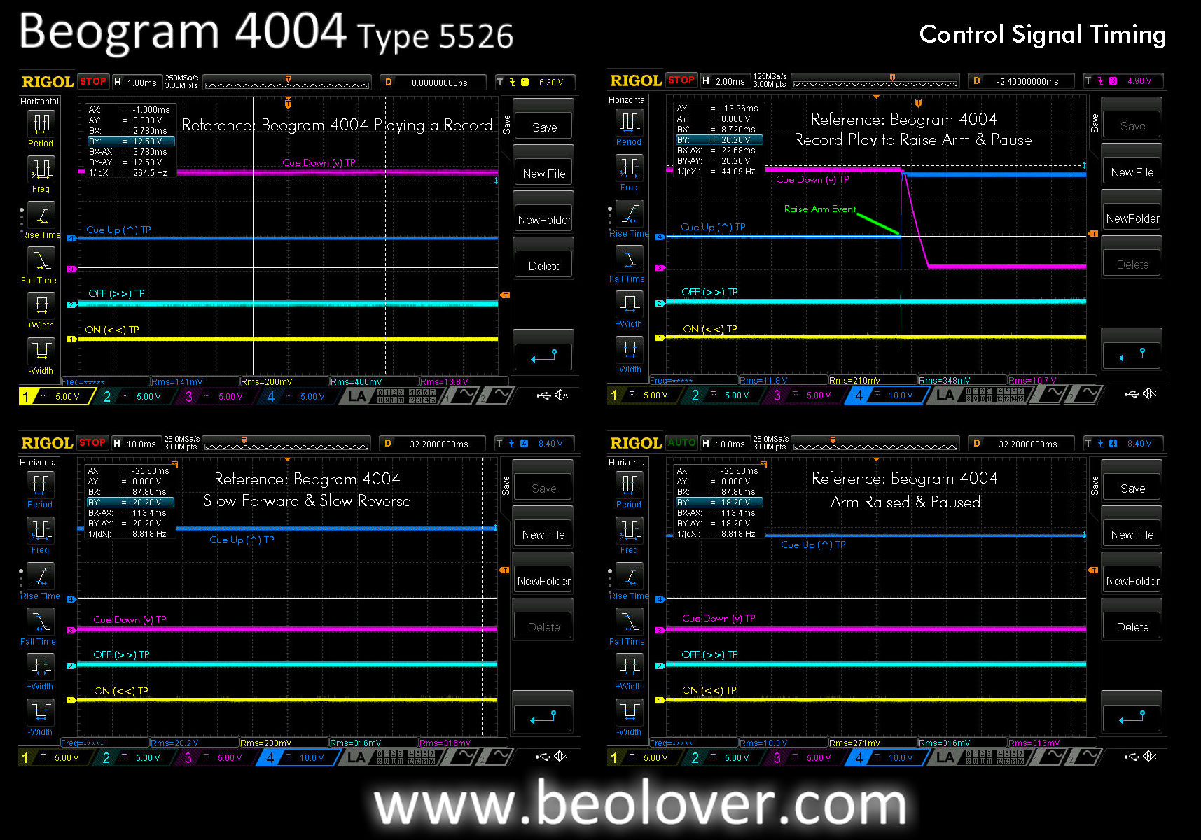
The following three pictures are oscilloscope screenshots for various Beogram 4004 events.

Viewing Tip: If the enlarged photo is too small to read the printed measurements, right-click the photo and select "Open link in new tab" or "Open link in new window".  The image in a stand-alone tab will allow you to zoom in for more detail.

In the first grouping I have a reference measurement of the four test points when the Beogram is turned off.  Next to it are the signal measurements when the START button is pressed.
Below those two measurements are the signals when the Beogram finds the set down point and lowers to play a record.  Last, are the signals when the arm is lowered and playing a record.


The next grouping continues with another picture of the control signals during record play.
That is followed by a cue up (arm raised), pause event.
The third picture shows the signals when the Beogram is operated in Slow Forward and Slow Reverse.
The final picture shows the signals when the Beogram is just paused over a record.

Note that the Cue Up signal is only active when the Beogram is in play mode and is either paused or scanning slowly (forward or reverse).  The Cue Up signal is off when the Beogram is scanning fast (forward or reverse) or cued down.


The final grouping shows the signals during the event where the Beogram is operated in Fast Forward mode until it reaches the ES (End Stop) switch and reverses to Fast Reverse.
The picture next to that is the event where the Beogram is in Fast Reverse mode and reaches the SO (Shut Off) switch.
The bottom left picture shows the event where the Beogram is cued down (playing a record) and the STOP button is pressed.  
The bottom right picture changes out the ON (<<) TP with the Run-Off Stop TP and shows the Run-Off Stop signal in relation to the OFF (>>) TP.


This photo shows the Beogram 4004 position sensor and scale that generate the Run-Off Stop signal.


This final photo of this post is another oscilloscope screenshot of the Record Detection circuit.
The test point is at the 1TR3 transistor collector and shows the signal generated by the Fixed Arm sensor over an empty platter (after processing through transistor 1TR3).


That is what I want to see.  A very healthy signal showing an empty platter.  The low part of the signal drops all the way down to zero volts and the peak is around six volts.  Very nice. 

This Beogram 4004 is performing great and in the next post I plan to wrap up the service manual adjustments.