Featured Post

Beolover SyncDrive: DC Platter Motor Replacement for Beogram 4002 and 4004 (Type 551x and 552x)

Late Beogram 4002 and the 4004 (Types 551x and 552x), which have DC platter motors instead of the earlier synchronous AC motors usually suff...

Showing posts with label SN1303006. Show all posts

Monday, March 22, 2021

A Pair of Beomaster 1900 Receivers for Restoration: Unit #2 Wrap Up

The second unit of the two Beomaster 1900 restoration projects is complete.

After letting the Beomaster 1900 play music through the night ...


...I was ready to reassemble the cabinet pieces.

I secured the Bass, Treble and Balance indicator masks back onto the slide controls


Then I fit the touch control panel onto the cabinet frame.
This can be a little tricky since the touch panel button actuators have to fit onto the button sensor posts.


Always check that all of the touch buttons are working before proceeding with the cabinet reassembly.


After the touch button control panel comes the tone control and FM tuning panel.
I applied some new Nyogel damping grease to the lid damper before securing the panel in place.


There are two rubber stops for the control panel lid to rest against when the lid is closed.
Those rubber pieces are always deteriorated and falling apart (if not already gone).
I made a replacement bumper pad with my 3D printer that fits where the original rubber pads were.


On the cabinet base plate I installed four new plastic cabinet feet that I ordered from Martin's Beoparts store.


The final piece was the smoked plexiglas that fits over the touch panel indicator lamps. I had removed it to polish it. It just slides back into place.

Now the Beomaster 1900 is ready for testing in a listening room.


Saturday, March 20, 2021

A Pair of Beomaster 1900 Receivers for Restoration: Unit #2 Performance Testing and a Volume Control LDR Problem

Today I finished some of the Beomaster 1900 service manual adjustments and began looking at its performance with THD (total harmonic distortion) and Frequency Response.

First a couple of service manual adjustments to make.
The Beomaster 1900 service manual calls for adjusting the tuning voltage for FM 1 and FM 5.
Specifically, the FM 1 tuning potentiometer (4R3) is to be set on the 88MHz dial position. 
With FM 1 selected as the Beomaster 1900 music source the 4R2 trimmer is adjusted so test point 4TP1 measures 4.5 VDC. 

Similarily, the FM 5 tuning potentiometer (4R7) is set to 88MHz.  With FM 5 as the selected music source trimmer 4R8 is adjusted to get 4.6 VDC ... also at test point 4TP1.

Here are those measurement and adjustment points.


The last service manual adjustment I made was to adjust the output level trimmer 2R136.
For this adjustment an input signal of 200mVrms, 1KHz (sine wave) is applied to the Beomaster 1900 Tape input. With the Beomaster 1900 volume preset on the middle setting the Beomaster is turned on by selecting the Tape source button. At that volume level the output of the Beomaster (as measured at the speaker outputs) should be at 100mV.  Trimmer 2R136 is used to adjust that level.

I set the test up by configuring a 200mVrms, 1KHz test signal out of the QuantAsylum QA401 Audio Analyzer.  I verified the signal with an oscilloscope then applied it to the Beomaster 1900 tape inputs.
I set the volume preset to the middle button and selected the Tape source button to turn the Beomaster 1900 on.  Then I measured the voltage at speaker loads.

Here is the test setup and the measurement results.


The left and right channels differ in output by 20mVrms. That isn't horrible but I expect them to be closer.

The Balance control was correctly in the center. The no-load current adjustments are almost identical.
I guessed that the problem must be in the Beomaster 1900 volume control LDR device.
That is a light controlled resistor device that uses a lamp whose intensity changes via electronic control. The amount of light then changes the resistance values of a set of photo resistors to control the Beomaster 1900 volume levels.

Just to investigate a little further I went ahead and checked the Beomaster 1900 THD (total harmonic distortion) at 30Watts (with 8 ohm dummy speaker loads). 


The THD values are good but the left channel is at about 20 Watts while the right channel is at about 30 Watts.

I needed to investigate the volume control LDR device.

Here are some photos of it.


Here is a photo of the volume control LDR device disassembled.
A single lamp in the center of the device emits light to four LDR devices.
When there is no light the resistance level of the LDR is at its highest and corresponds to full volume of the Beomaster 1900 amplifier.
As the lamp begins to emit light the LDR resistance decreases and attenuates the audio signal.


The photo shows four LDR devices around the lamp in the volume control device.
Two LDR devices are for the left channel and two are for the right channel.
One set (L & R) are for voltage levels in the tone control circuit and the other set (L & R) are for the voltage level in the output amplifier.

To test this device out I connected the two wires for the lamp to a DC power supply and set the voltage to 5 VDC.  Then I measured the resistance of each of the four resistors to see how close in value they were to each other. 

I discovered that the four LDR devices in the volume control of this Beomaster 1900 unit did not have a consistent resistance value for my test voltage.

I measured several LDR devices with my test setup and selected four LDR devices that were very close to each other in value. 

I reinstalled those into the volume control casing and then back into the Beomaster 1900.
Then I repeated the Tape input level adjustment.

This time the difference in the left and right channel is about 7mVrms.  That is much better than the previous 20mVrms difference.


What about the left and right channels at maximum power output?

The Beomaster 1900 spec sheet says the maximum power output of the Beomaster 1900 amplifier is rated at 2 x 20 W/8 ohms. The maximum total harmonic distortion is listed as less than 0.2%.
Due to the nature of the touch sensitive volume control it is difficult to dial in a precise volume level for this check.  I ended up with measurements at output levels of 15W, 28W and 32W.

All three measured well below the target 0.2% THD value.

Here is the THD measurement at 28 Watts across my dummy 8.1 Ohm speaker loads.


Those are nice distortion percentages and at a higher output level than the specification sheet.
Also notice that the left and right channel output levels are much closer to each other than before I worked on the volume control LDR device.  I am satisfied with these results.

The last test is a frequency response test. I set the voltage level to output 26W of output from the Beomaster 1900 amplifier across the 8.1Ohm dummy speaker loads. 
Here are the measurements from my QA401 Audio Analyzer.


That measurement is right in line with what I have been seeing on the Beomaster 1900 and 2400 amplifiers. The frequency response is comfortably between ±1.5dBV from 20Hz to 20KHz.  This Beomaster 1900 is actually performing at ±1dBV through that frequency range. Plus that is above the expected maximum output level. 

I will continue on with the reassembly of the Beomaster cabinet parts then put the unit into listening testing.

While I am doing that I will begin a couple of fun Beogram turntable restorations and a change of belts on a Beogram CD50 unit.


Friday, March 19, 2021

A Pair of Beomaster 1900 Receivers for Restoration: Unit #2 Reassembly and Power Supply Checks

This second Beomaster 1900 unit is ready for reassembly and its initial power supply checks.

I put the power transistor heatsinks back in place on the four output transistors. I used Sil-Pad insulators for the thermal insulation material.

As a reminder, here is what the power transistors looked like at the start...prior to the capacitor replacements.


Here they are now after the restoration.  Installed with their new thermal insulation.


This photo shows the trace side mounting of the heatsinks.


While I had the heatsinks installed and the Beomaster 1900 turned over I soldered on some test leads for the No-Load Currrent measurements I will be adjusting later.


Next is the reassembly of the indicator lamp boards. I use dual LED lamp assemblies for the Bass, Treble and Balance slider position indicators.  For everything else I use replacement incandescent lamps.


While access is easy to the Beomaster 1900 touch button posts I cleaned the posts and treated them with Deoxit.


I had to resolder the power transformer secondary wires that supply the Beomaster 1900 +15VDC power supply.  That is because I intentionally desoldered them to protect them while I was moving the board around during the capacitor replacment.


Power could now be applied to the Beomaster and the standby lamp indicates there is +15 VDC power.


I tested and adjusted the Beomaster +15 VDC supply voltage per the service manual first.
The voltage coming in from the transformer secondary was the usual voltage of over 22 VDC.


I then performed the service manual adjustment to set the regulated +15 VDC supply to +15.0 VDC.


Next I did a quick check to verify the +-31 VDC rail voltages were present...and they were.


The power supplies look good so it is on to making an initial No-Load Current adjustment.
Per the service manual I adjusted the no load current for the output amplifier emitter resistors where the DC voltage across the emitter resistors is 12mVDC.  That measurement is also made without any speakers connected (no load) and with the volume level at zero.


This is a good start to the Beomaster 1900 restoration wrap-up.
Tomorrow I will finish the service manual checks and run some performance checks.


Sunday, March 14, 2021

A Pair of Beomaster 1900 Receivers for Restoration: Capacitor Replacement and Slider Controls on Unit #2

Unit 2 of the pair of Beomaster 1900 restoration projects is ready for reassembly now.


I finished all of the capacitor replacement tasks (fifty-eight from the main board, seventy-four in total) and repaired the Bass and Treble tone control sliders. 

First was the Volume Control board.  Six capacitors to replace there.

Here is the before photo.


Here is the after photo.


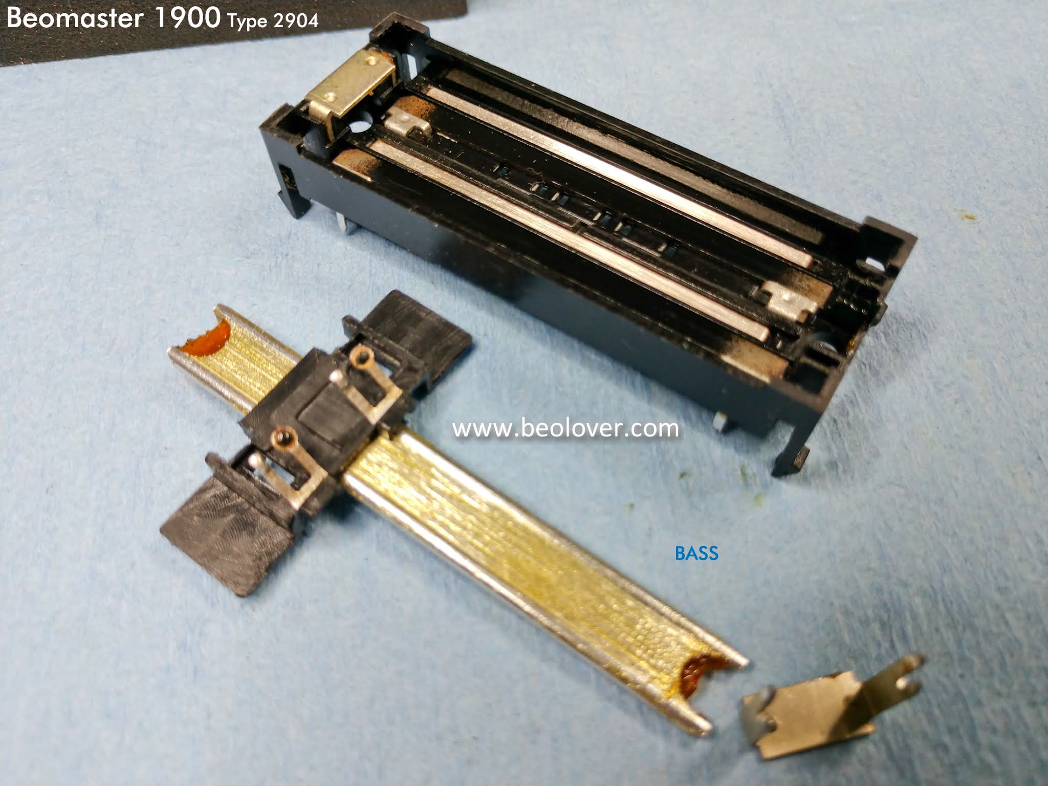
Finally, the Tone Control and FM Tuning board.  It only has ten capacitors to replace but it also has the Bass, Treble and Balance slider controls. They need a good cleaning plus the Bass and Treble controls have broken slider bridges that hold the switch contacts in place.

As usual I will use the repair kit for the sliders from Beoparts.

Here is the before photo for the capacitor replacements.


With 74 capacitors to replace plus a few other components there is no way I would attempt that without a de-soldering gun. 


Here is the after photo.


Just like the first Beomaster 1900 restoration (Unit 1 of the pair), the Balance slide control was good and only required a good cleaning.

The Bass and Treble slide controls however, had the usual broken tabs on the slider bridge that holds the contacts.  Here is the Bass control removed and repaired.


...and here are the Treble and Balance controls.


Here is the completed slider control repair and some of the key tools used in the repair.


Next comes the reassembly of this Beomaster 1900 then the power supply tests.