Featured Post

Beolover SyncDrive: DC Platter Motor Replacement for Beogram 4002 and 4004 (Type 551x and 552x)

Late Beogram 4002 and the 4004 (Types 551x and 552x), which have DC platter motors instead of the earlier synchronous AC motors usually suff...

Showing posts with label 210TCBG4002. Show all posts

Sunday, November 12, 2017

Bang&Olufsen MMC20EN Vintage Cartridge Test

The Beogram 4004 parts that I recently restored came with a MMC20EN cartridge, which was to be tested.

There are two preceding posts about my (still evolving - Beolove never ends..;-) approach to cartridge testing. One outlines the test of the frequency range of a cartridge and the other discusses testing the 'trackability', i.e. how well can the cantilever track deflections in the groves of the record. This essentially tests the mechanical aspects of the cartridge, most notably the state of the cantilever suspension.

I currently use three test records:
1) The Analogue Audio Ultimate Test LP. This record has a pink noise track that is perfect for checking the frequency response of the cartridge in the audible range. Unfortunately, this track tops out at 20kHz, and so we need to use a different record to see if the cartridge can also reproduce higher frequencies.
2)  The Fisher Test & Performance Standard Quadradisc: This record has some CD-4 quadraphonic tracks which feature the 30 kHz carrier frequency that is needed to encode the two back channels. The test tracks have this carrier without any encoded sound, which is a great way to see if the cartridge can reproduce 30kHz.
3) The Clearaudio Trackability Test Record: This record is used to determine the condition of the cantilever suspension. It has 333 Hz tracks with different groove amplitudes from 50 um to 100 um.
This allows a measurement of how well the cantilever can deflect and at what deflections significant distortions occur that would negatively affect the sound quality.

Aside from these test records an audio analyzer with the capability to calculate a Fourier transform of the voltage signal coming from the cartridge is required. I use the QuantAsylum QA400 (now replaced by the QA401), which (aside from a somewhat lackluster user interface) is a very capable device that has a high sensitivity enabling plugging the turntable directly into its input without needing amplification. This allows analyzing the signal from the cartridge directly. I simply use a DIN to RCA adapter and connect the DIN5 of a Beogram directly to the analyzer input.

These are the results measured on the MMC20EN cartridge (at a tracking weight of 1.2g):

This is the 20 Hz to 20 kHz frequency response of the cartridge as measured with the pink noise track:


And this is the CD-4 carrier signal (sharp peak at 30 kHz):
The amplitude of this peak is supposed to be 1/10 (or -20 dBV) of the 0 VU 1 kHz signal, which is usually at about -47 to -50 dBV. The peak measured in the graph is at about -70 dBV, which is about where it should be. So far so good!

These are the results of the trackability test:

I used the 50, 60 and 70 um 333Hz test signals on the Trackability record. The 50 um track corresponds approximately to a 0VU signal, which is normally the maximum amplitude encountered on a standard record. The 60 um amplitude level approximately corresponds to a +6 dBV signal level. I measured these THD percentages:

50um left:     1.8%
50um right:   3.5%
60um left:     2.8%
60um right:   10%
70um left:      4.9%
70um right:    20%

Since THD levels up to 5% go unnoticed by most human listeners, this cartridge can still be used for records that adhere to standard amplitude levels, but at +6dB amplitudes distortions will be audible on the right channel...

Tuesday, April 4, 2017

Test of a Vintage Bang & Olufsen MMC4000 Cartridge

The Beogram 4002 (5513) that I recently restored came with a MMC4000 cartridge, which was to be tested. You can listen to this particular cartridge in the latest CleanerVinyl Before/After demo video that we made on the occasion of adding Freddie Hubbard's album "Polar AC" to our collection. You will hear that it sounds pretty good. Let's see if the measurement conforms...;-):

There are two preceding posts about my (still evolving - Beolove never ends..;-) approach to cartridge testing. One outlines the test of the frequency range of a cartridge and the other discusses testing the 'trackability', i.e. how well can the cantilever track deflections in the groves of the record. This essentially tests the mechanical aspects of the cartridge, most notably the state of the cantilever suspension.

I currently use three test records:
1) The Analogue Audio Ultimate Test LP. This record has a pink noise track that is perfect for checking the frequency response of the cartridge in the audible range. Unfortunately, this track tops out at 20kHz, and so we need to use a different record to see if the cartridge can also reproduce higher frequencies.
2)  The Fisher Test & Performance Standard Quadradisc: This record has some CD-4 quadraphonic tracks which feature the 30 kHz carrier frequency that is needed to encode the two back channels. The test tracks have this carrier without any encoded sound, which is a great way to see if the cartridge can reproduce 30kHz.
3) The Clearaudio Trackability Test Record: This record is used to determine the condition of the cantilever suspension. It has 333 Hz tracks with different groove amplitudes from 50 um to 100 um.
This allows a measurement of how well the cantilever can deflect and at what deflections significant distortions occur that would negatively affect the sound quality.

Aside from these test records an audio analyzer with the capability to calculate a Fourier transform of the voltage signal coming from the cartridge. I use the QuantAsylum QA400 (now replaced by the QA401), which (aside from a somewhat lackluster user interface) is a very capable device that has a high sensitivity enabling plugging the turntable directly into its input without needing amplification. This allows analyzing the signal from the cartridge directly. I simply use a DIN to RCA adapter and connect the DIN5 of a Beogram directly to the analyzer input.

These are the results on this particular MMC4000 cartridge (at a tracking weight of 1.2g):

This is the 20 Hz to 20 kHz frequency response of the cartridge as measured with the pink noise track:


And this is the CD-4 carrier signal (sharp peak at 30 kHz):


The amplitude of this peak is supposed to be 1/10 (or -20 dBV) of the 0 VU 1 kHz signal, which is usually at about -47 to -50 dBV. The peak measured in the graph is at about -65 dBV, which therefore is about where it should be. So far so good!

On to the trackability test:


This graph shows the total harmonic distortion of the 333Hz test signal. The 1kHz signal is a standard mono 0 VU signal, i.e. represents the highest amplitude normally encountered on a regular vinyl record. The other measurements are at 333 Hz, and the 60 um amplitude level approximately corresponds to a +6 dBV signal level. Since THD levels up to 5% go unnoticed by most human listeners, this cartridge can still be used for records that adhere to standard amplitude levels.

Monday, March 27, 2017

Beogram 4002 (5513): Final Adjustments and Test Drive with Freddy Hubbard's 1975 Album "Polar AC"

It is always a happy moment when a restoration concludes and another Beogram 4002 sits there in pristine Beoloving happiness playing a favorite album! However, before I was able to enjoy this moment with Freddie Hubbard, the final adjustments had to be done to this Beogram. The first step in the adjustment process is always to get the platter and arms perfectly aligned. The next step is to align the platter with the aluminum panels that surround it, while keeping the chassis floating freely suspended by the spring loaded arms that pull it up. This can be a difficult process since there is very little leeway to get all these parameters properly adjusted.

Once this is accomplished the arm lowering limit needs to be adjusted. This is a very important adjustment since it is the final safeguard against needle loss should the record detection mechanism malfunction. You may have wondered why the ribs on the platter have U-shaped recesses...their main purpose is to give the needle some space in case it is lowered accidentally due to a malfunctioning photodiode in the sensor arm or a confused control system. The lowering limit needs to be adjusted that the needle clears the ribs in those U-shaped troughs:
Once this is done, the tracking force can be adjusted. I usually replace the flimsy circlip that holds the  counter weight in place with a nut that can be tightened. This gives this mechanism much mor longterm stability and it stays calibrated during shipping. This shows the original setup:
and with the M3 nut tightened in place:
Then the weight can be adjusted. I always adjust everything that the adjustment scale is accurate around the 1.2g mark which is the recommended tracking weight for most B&O cartridges:
One more thing before the test drive: This Beogram had missing hood mounting springs. They often get lost when people unscrew the hood mounting bolts. Luckily one can replace them with the springs from Pilot G-7 pens which have a larger than usual diameter cartridge:
I cut them in half and widen their diameter a bit on one end. This allows to fit them to both of the hood mounting bolts:
And the it was time for the test drive. I selected Freddie Hubbard's "Polar AC" album, which he recorded in 1975 for the CTI label. It has some quite awesome tracks on it. My favorite is "People Make the World Go Round" (which has another great interpretation on CTI by Milt Jackson - I'll feature this one some other time on a different 4002!). Anyway, here is an impression:
This near-mint first release record was restored to its original glory with the CleanerVinyl Pro ultrasonic record cleaning system. In fact, we used this lovely restored Beogram to make a before/after video that demonstrates how impressively how well ultrasonic vinyl cleaning works by featuring the People Make the World Go Round track before and after cleaning in a video:
Enjoy!


Wednesday, March 22, 2017

Beogram 4002 (5513): Replacement of the Sensor Arm Bulb with an LED and Improvement of the Record Detection Circuit

On the way to an all-LED Beogram 4002 the replacement of the sensor arm LED is usually my final step. And so, after restoring the DC motor, it was time to implant my recently developed flex-PCB based LED assembly to replace the incandescent light bulb. This shows the sensor arm with pulled out detector assembly:
If you click on the picture to get the full resolution and magnify it a bit on your screen, you will see that there is already a small black spot on the glass bulb, indicating that significant tungsten evaporation has taken place from the filament. This points to a likely near term demise of this bulb, which would incapacitate the Beogram. The installation of a LED promises a much better long term stability, and this is the main reason for LED upgrades outside the scarcity of fitting small light bulbs - they are hard to find these days.
The challenge with this particular LED upgrade is of course the small space and the need to replicate the power draw of the light bulb to not confuse the record detection circuit (see below).

My LED replacement therefore contains an additional resistor that compensates for the much lower power draw of the LED (which is a high brightness low color temperature model running at a very low emission level). This shows the assembly:
It is built based on a flex-PCB that can fold into the bulb compartment:
The glued on 3D printed red wedge on top assures that the LED sits in a place comparable to the bulb filament.
This shows the assembly in action:
Note the accurate color of the B&O logo, which is a result of the use of a low color temperature LED which has a high red component.

Any light source replacement in the sensor arm should be accompanied by measuring the sensor response when the arm is over a spinning empty platter to verify that the signal is strong enough to precisely and reliably trigger the protection circuit that prevents arm lowering in absence of a record. This is the trace I measured on the collector of TR3 after installing the LED:
On first glance it looks textbook, the dips going all the way until they bottom out at 0V. However, closer examination yields that the amplitude of the signal is only about 3.7V, while the circuit diagram prescribes something closer to 6V. This amplitude is too small to reliably trigger the protection circuit.

This shows the pertinent part of the circuit diagram:

This is how it works: The base of TR3 is biased by the voltage divider formed by R26 and the BE-diode in the transistor. The signal from the photocell in the sensor arm OPH1 is coupled in via C12. When there is no signal (like over a record), the voltage at the base is such that the collector of TR3 is at 4V. This means that the transistor is slightly ON creating a voltage divider with R27 (and R30). When OPH1 delivers its AC signal of about 20 mV amplitude, the voltage at the TR3 collector starts oscillating between 6 V and 0 V, i.e. TR3 operates as an amplifier. This 6Vpp signal is then fed into the base of TR4 via C16, which takes out the DC component. Since the base of TR4 is pulled up to 21V via R32 and protected against negative voltage (relative to its emitter) by D15, the resulting signal at the TR4 base is an oscillation between 21.6V and 20.4V. While at 20.4V the transistor is on, and C18 charges. This in turn biases it towards 21V. This pulls up the base of TR6 via R34 as current limiter and the collector of TR6 is pulled to ground. This signal then prevents the arm lowering circuit to work and the arm stays up.

There is a second way to pull up the base of TR6, which is via the D18/R37 link. This connects to the collector of TR5 via the Zener diode D17. This is the circuitry that can invoke the 'no record present' signal at the collector of TR6 if the light bulb is broken. If the light bulb is open circuit, no current flows in R36, causing the voltage at the collector of TR5 to go up. This pulls up the base of TR6 and the collector of TR6 goes down and the arm cannot be lowered anymore under any circumstance. This is the reason that the LED replacement needs to be designed in a way that the current through TR5 is similar to the current caused by the original light bulb (~50-60mA).

Back to the signal on the collector of TR3, which measured to be less than 6Vpp. I long ago noticed that some Beograms have issues with the detector circuit and that sometimes they do not recognize that there is no record and happily lower the arm on the platter even though everything seems to be in working condition. If that happens the stylus' life depends on the proper adjustment of the arm lowering limit keeping it from hitting the platter ribs.
I addressed this problem in the past by soldering in a 10M resistor between the base of TR4 and GND. This biased TR4 slightly on and even a weaker signal from TR3 would be enough to stop the arm lowering circuit. At that point I did not understand the root-cause of the problem, but rather discovered the fix by accident: The circuit tended to work whenever I connected my oscilloscope to the base of TR4 and I realized that the internal resistance of the scope fixed the problem...a bit of trial and error yielded that a 10M resistor to GND tugged enough on the base of TR4 to keep things working after disconnecting the oscilloscope.

But as I know now, there is a much better solution: Double R26 to 2M. This causes a reduction of the current through the BE diode of TR3, and so the transistor is less on, and the voltage at the collector goes up to the prescribed 4V. This fixed the problem in this Beogram:
The amplitude of the oscillation is now close to 6V and can trigger TR4 reliably.

An interesting question is: Why did B&O let Beograms leave the factory with 1M resistors in place and a too low TR3 collector voltage?

One of the issues with the design around TR3 is that the collector voltage depends on the DC current gain of the particular transistor used as TR3. The current gain is the most variable parameter of any transistor series, i.e. even within one production run it can vary considerably by up to a factor two or three. It would have been better to bias the base with a stiff enough voltage divider to GND, and to implement a feedback for setting the gain of the amplification. With the design as it is, every Beogram has in essence a different TR3 working point depending on the particular BC182 that is soldered in. With a new light bulb in place in the sensor arm this variation may not have been a problem due to the high initial light intensity making enough signal even with a non-spec working point of TR3. But as the bulbs aged the intensity gradually went down due to deposited Tungsten on the bulb glass. And after a while the signal became weaker and at some point the mechanism stopped working. So they may not have noticed back then that there is a problem when they manufactured these Beograms.

Interesting stuff (at least to the Beolover...;-)!


Tuesday, March 21, 2017

Beogram 4002 (5513): DC Motor Restoration and Yet Another Exciting Aspect of Achieving RPM Stability

The restoration of the platter drive system of a DC motor Beogram 4002 (5513) requires the installation of modern multi-turn RPM trimmers, a new encapsulated RPM relay, replacing the light bulbs that back-illuminate the user accessible RPM trimmers with LEDs for better thermal stability, and rebuilding the motor with freshly oil infused oilite bearings. See here for RPM measurements taken after each of these steps to see how they individually improve the RPM stability.

The Beogram 4002 that is currently on my bench already received most of the above treatment except the motor restoration. And so here we go:

This shows the extracted DC motor:
To get to the bearings the motor needs to be fully taken apart:
The bearings are the two small donuts on the black pad.
Once the bearings are out, they need to be oil-infused. They are made from porous "Oilite" brass that is factory oil infused. After some run time the oil in the bearings is depleted and it needs to be replaced. This needs to be done under vacuum to draw out the air from the pores that over time replaced the oil. This shows the bearings in a mason jar under SAE30 oil after pulling the vacuum:
The air bubbles show that the oil infusion process has started. When the bubbling stops after 12 to 24 hrs, the process is finished.
Then it is time to put the bearings back into the motor housing.
This shows the bottom bearing re-inserted into the brush carrier plate (which also contains the white feedback coils for the tacho control of the motor):
This shows the process putting the top bearing in:
I use special 3D printed fixtures to press the tabbed ring back onto the bearing to hold it in place securely:
Once the motor is back together it is time to give it an initial test. Run it at ~5V and measure the current. It should be <30mA. If it is higher then the brush carrier plate needs to be loosened and retightened until the current is low enough. This ensures that the motor spins easily for good long-term stability.

Then it is time to put the motor back in and do a multi-hour RPM characterization. I usually run them for 12-24 hours. This usually shows if there are any problems left to tackle or if the motor is good to go. This shows the measurement process with my Beolover RPM device:
It clamps on to the Beogram frame and delivers a stream of RPM measurements to a computer serial port, which allows graphing the RPM stability over time. It is available to other enthusiasts. Just send me an email or use the contact form on the right. The blue curve is what I measured after the above procedure:
And that was a pretty disappointing result! Pretty big RPM spikes towards higher RPMs. Absolutely Beounlovely!

After a bit of head scratching I decided to put the motor into my own Beogram 4002 5513 and run it there. It performed flawlessly as expected after the oil infusion procedure. Then I ran the motor again with my main PCB installed in this Beogram. Again, flawless performance! This pretty much narrowed the problem down to an issue with the main board of this Beogram. I compared the two boards and I realized that C10 on my board had a 10 uF capacitor installed, while the board in this Beogram had a 0.47 uF capacitor installed. I had noticed in the past that some Beograms have 10 uF, while others have 0.47 uF or even 0.33 uF installed as C10.
I replaced the 0.47 uF capacitor with 10 uF and voila! I was able to measure the red curve in the above graph. So we can conclude that it is a good idea to replace C10 with a 10 uF capacitor if there still are RPM issues after doing all the other tasks outlined above to make the system stable.

Of course I wondered why a smaller C10 causes these RPM fluctuations. This shows the control circuit of the DC motor on the PCB:
C10 is the smaller capacitor to the left of the C1003 motor control IC. This shows the circuit that controls the motor:

Essentially, the motor induced feedback ("tacho") signal from the small coils in the brush carrier plate shown above is fed into an amplifier at pin 1. The overdriven amplifier changes the sinusoidal feedback signal into a square wave, which is compared with a time constant network formed by the RPM trimmers and C3 in the Schmitt trigger. This results in a square wave with a duty cycle that now depends on the motor RPM. If the motor RPM is too low the duty cycle increases. If the motor is too fast the duty cycle becomes smaller. That way C8 is charged to different voltages, which changes the DC voltage at pin 5 that controls the amplifiers that control the current that goes into the motor.

The sensitivity of this process is controlled by the feedback fed from pin 4 into pin 5 via the C10/C9/R20 voltage divider. Depending on C10 this feedback gets stronger or weaker. Since the feedback voltage divider is build from capacitors it is essentially only active when the motor voltage changes at pin 4. The impedance of a capacitor is 1/wC (w being the frequency). This means that the impedance of C10 is smaller for 10 uF than for 0.47 uF. This means that the voltage divider tries to reduce voltage spikes across the motor more resolutely, tamping down more resolutely on sudden changes. 

In other words the system becomes slower and less severe in its reaction to RPM changes, which we clearly see in the red curve. It appears to me that 0.47 uF leads to an overreaction of the system and even the establishments of a number of unstable oscillatory states. This can be inferred from the tendency of the blue curve to always jump to similar RPMs. Essentially, it flip-flops between several RPM states in a random way.

The fact that some Beogram 4002 were already factory-fitted with 10 uF (while the above diagram from the service manual shows 0.47 uF) indicates that B&O at some point realized this problem and took corrective action. I'd love to get my hands on this service bulletin! It was probably not so simple in the 70s to quantify long term RPM aberrations due to the absence of digital tools like my Beolover RPM device.


Sunday, March 19, 2017

Beogram 4002 (5513): RPM Trimmer Illumination Very Low

After restoring the PCBs of this Beogram 4002 (5513) it was time to address the very low background illumination of the 33 and 45 RPM trimmer scales. I removed the RPM trimmer panel and put it on the bench:
After removal of the light shields the bulbs can be accessed:
A closer examination revealed that the bulbs had been replaced at some point with non-spec units resulting in the too low light intensity. As usual, I replaced these bulbs with my SMD LED based implants:
Like all my parts they are available to other enthusiasts. Just send me an email or use the contact form on the right. They are direct drop in replacements for the light bulbs:
The design allows for putting the covers back in place:
The combination red and green LEDs of the replacements generate a warm incandescent-like light that not only looks authentic, but also properly illuminates the red scale hands of the RPM trimmer displays:
Beolovely! These displays are back in business!


Saturday, March 18, 2017

Beogram 4002 (5513): Restoration of PCBs and Reservoir Capacitors

After rebuilding the tonearm and drive carriage systems of this Beogram 4002 (5513), it was time to address the electronics. The first step is always to replace all electrolytic capacitors and RPM trimmers and relay to ensure trouble free operation in the decades to come. This shows the main PCB in its original condition:
And after replacing the components:
This shows the RPM control section in detail:
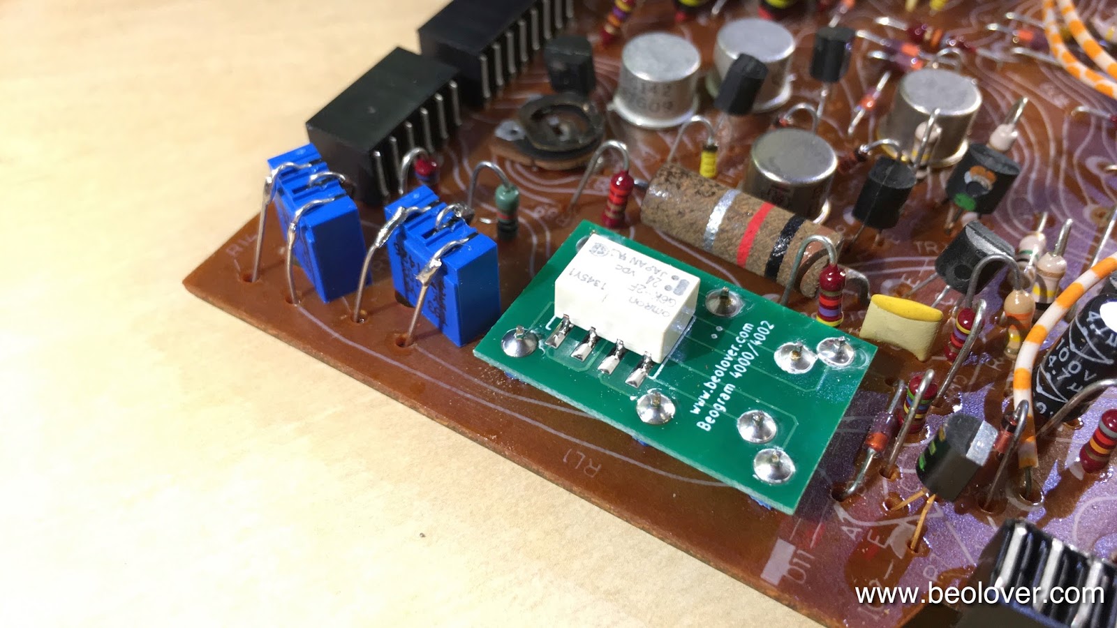
The replacement relay is a Beolover design that matches the footprint of the original Siemens relay:
These replacements re available to other enthusiasts. Just send me an email or use the contact form on the right. On to the reservoir capacitors. This shows the original dual capacitance unit:
This is a unique design containing two common grounded capacitors with 4700uF and 1000uF capacitances. These capacitors are not made anymore and so they need to be replaced with two individual units. To keep things organized, I designed a 3D printed fixture that holds things in place:
and from the back:
It fits precisely into the same spot and the original mounting clamp can be used to hold the assembly in place. This assembly is also available.
The final step was to replace the relay and single electrolytic capacitor on the output PCB. This shows the original board:
And with the replacement parts:
The red switch is an upgrade that I designed. It allows to connect system and signal grounds in case there are humming issues (mainly when connecting the Beogram to an amplifier with RCA inputs). 


Friday, March 17, 2017

Beogram 4002 (5513): Restoration of Arm Lowering and Tracking System

After the first evaluation of this Beogram 4002 my starting point of its restoration was as usual rebuilding the arm lowering and tracking systems. My customer already did the cleaning and lubricating of the damper and solenoid linkages, so all that was left was to remove the linkage between the damper and the tonearm. This requires taking out the sensor arm assembly. This shows the arms from the back:
Taking out the sensor arm requires removal of two screws at its base:
Then the linkage can be removed:
After cleaning and lubricating the bearing I put the arm back together and bolted it back onto the carriage. Then it was time to adjust the arms orthogonal to the carriage tracks and parallel to each other:
Once this was done, I installed my LED based tracking sensor light source replacing the incandescent lightbulb that originally illuminates the tracking sensors. This shows old and new light sources in direct comparison. The LED is in exactly the same spot as the filament of the bulb:
On the back of the LED unit the blue trimmer is used to adjust the light intensity. This makes it much more straight forward to adjust the tracking sensor sensitivity:
This shows the original light source in place:
And the replacement:
The final step of the carriage restoration was to clean the threaded rod that advances the carriage and put a new pulley on. This shows the original cracked and glued on (shudder!) plastic pulley:
After breaking it loose in pieces from the rod the new precision turned aluminum pulley could be installed:
Very Beolovely, if you ask me! If you wanted to upgrade your 400x to a pulley like this, send me an email or use the contact form to the right. I'll be happy to get you in touch with the Master of Pulleys! By the way: All my parts featured on this blog are available to other enthusiasts, too! On to restoring the electronics!