Featured Post

Beolover SyncDrive: DC Platter Motor Replacement for Beogram 4002 and 4004 (Type 551x and 552x)

Late Beogram 4002 and the 4004 (Types 551x and 552x), which have DC platter motors instead of the earlier synchronous AC motors usually suff...

Showing posts with label 108GMBG4002. Show all posts

Sunday, April 24, 2016

Beogram 4002 (5513): Restoration of DC Platter Motor Bearings with Oil Infusion Under Vacuum

While I am having the Beogram 4002 (5513) that lost its solenoid plunger on my bench, I decided to redo the DC motor. When I initially restored this deck I did not know yet that one needs to infuse the brass sleeve bearings with oil under vacuum if the fix is supposed to have lasting effect. Just putting some grease on the bearings quiets them down temporarily and stabilizes the RPM performance, but after a few weeks usually the effect of the grease wears off and RPM variations start occurring again.

Here are a few impressions of the process. The motor needs to be completely disassembled to get the bearings out (and more importantly, back in):
The next step is to infuse the bearings with oil under vacuum. I use a mason jar and a FoodSaver vacuum pump for that. As soon as the vacuum is established air bubbles arise from the bearings:
This is a result of the expansion of the air in the pores in the brass due to the low pressure in the jar. The escaping air makes room for the oil that can then diffuse into the bearing.
A typical Oilite bearing contains about 20% oil by weight. This is enough to provide an oil field on the bearing surface for many hours of motor operation.
Once the bubbles stop (typically takes about 12-24 hrs) the bearing is full of oil again and there motor can be reassembled. This shows the brushes carrier plate with the bottom bearing reinserted:
The top bearing is held in place with a ring whose tabs need to be forced back flat to hold the bearing in place securely. I designed a special tool for this task that allows me to use adjustable pliers to press the tabs down:
The red cylinder goes inside the motor housing and the orange part is used to press the tabs down against the red part. This results in a bearing that sits snugly in its cradle below the top shaft orifice:
Once the bearings are back in, the motor can be put together and the PCB soldered back on:
At this point the motor needs to be tested with a bench supply. It is imperative that the brushes carrier plate is installed in a way that the rotor rotation is not impeded. This can be reliably quantified by observing the current that the motor draws while spinning freely at 5V. In my experience the lowest current that can be achieved is below 30mA. If there is too much friction the current will be higher. If that is the case the bottom plate needs to be loosened and carefully retightened while turning the screws in small steps in sequence until they are tight. It can take a few attempts until the lowest current can be achieved.  This shows my bench supply with the motor running after I was done with this process.
Once the current is right, the motor can be inserted into the outer noise canceling shell and then reinstalled in the Beogram.
It is a good idea to test the motor for a few hours to make sure that everything is stable and up to specifications. I did that with my BeoloverRPM device that allows to measure the RPM over time and log it via the serial port of a computer. This is the graph that I measured for this motor over about 8 hrs:
This looks as it should! This Beogram 4002 is ready to be shipped back! Hopefully this time it will stay away a bit longer!


Saturday, April 23, 2016

Beogram 4002 (5513): A Broken Off Solenoid Plunger and New Transport Lock Bushings

Oh well...a sad moment: A Beogram 4002 (5513) that I recently sent back to a customer already returned. A few weeks after a happy report of enjoying vinyls on the newly restored 4002 (via my recently developed internal Beogram RIAA pre-amp) an email reached me stating that the tonearm would not lower anymore. So the deck was packed up again and it came back to my bench. What I found was pretty astonishing:
If you look closely, you see that the solenoid plunger went missing. No surprise that the arm did not lower anymore...nothing to there for pulling the linkage that activates the damper, and with that the arm lowering mechanism. So I went looking for the plunger. After taking out the sub chassis
I finally found it:
The amazing thing here is that the end of the hook that grabs the linkage broke off...I never saw such thing before, but I guess material fatigue can hit the most unlikely places.

The only solution for this issue was to replace the solenoid with a unit from a parts 4002 that I bought on ebay a while ago:
After this implantation the mechanism worked again. While I had the sub-chassis out it became apparent that the transport lock bushings did not survive the return trip and that they needed to be replaced. This shows the detritus of the front lock bushing:
I should have replaced them during the first 'visit' of this Beogram, but they looked o.k. then and so I left them. I think it can be said with some certainty that all orange looking bushings need to be replaced at this point in time. The grey ones seem to survive better.

I replaced all three bushings with my nylon replacement parts printed by Shapeways:
Each bushing is replaced by two of these parts, one goes in from the top and the other one from the bottom:
This shows the left-side lock put back together:
There is a video about installing new transport lock bushings in my Beogram 4002 playlist. The bushings can be ordered directly from my Shapeways store. This is the link to the part. Two are needed per transport lock.

Allright...this Beogram is on the mend. However, before I send it back, I will give the DC motor my oilite bearing oil infusion treatment. When I initially 'rebuilt' the motor of this Beogram, I did not know yet about the necessity of infusing the brass sleeve bearings of the Beogram DC motors with oil under vacuum. This is the only way to re-lubricate the bearings with lasting effect that the motor can serve another 30 years...this is Beolove!


Monday, March 14, 2016

Beogram 4002 (5513): Repair of Bent System Ground Terminal

After installing my new BeoloverRIAA pre-amplifier design in the Beogram 4002 that I just finished up, I set out to put the enclosure back together and bolt on the hood when I realized that I had completely forgotten about the bent and damaged system ground terminal in the back:
It turned out that I needed to cut the bold off with a saw since the threads were too damaged to get the  rusty nut off that was installed. After getting the bolt out I installed a new 3 mm bolt with the appropriate insulating shoulder washers:
O.k...it seems I am done now! Beolove is in details! Time to ship this 4002 back to its owner!

Saturday, March 12, 2016

BeoloverRIAA Preamp: First Installation of Finalized Design in Beogram 4002

I received the redesigned PCBs for my Beogram 4002 internal RIAA pre-amplifier a couple days ago. The fact that this pre-amplifier runs from the single rail Beogram-internal power supply posed some interesting design challenges that made it necessary to go through a couple of design interactions to achieve a satisfying signal-to-noise ratio. See my previous post for more details on the design process.

But now I think this design is ready for primetime. I populated one of the boards and implanted it into  a first Beogram 4002. Here are a few impressions. This shows the redesigned board with its 3D printed mounting support:
The board grew a bit in size to accommodate my improved power supply design.
This shows the mounting support on the pins of the board:
The pins fit directly into the solder points of the original output relay of the Beogram 4002. In fact, the RIAA preamp board maintains the full functionality of the non-amplified standard output of the Beogram. That is the reason that there are two relays on the board. One for the amplified output and one performing the function of the original output relay
This means the user can easily switch the deck between RIAA and standard output by simply plugging the connectors either into the amplifier board or into the original connectors on the output board (see below).
This shows the board installed on PCB 8. I had to move the grounding switch that I had initially installed to a different location underneath the original input connector:
This shows PCB 8 installed back in the Beogram 4002:
The input and output connectors are shown inserted into the amplifier board, i.e. this is the configuration for amplified output. The original non-amplified output can be configured by inserting the connectors into the original board-to-wire connectors on PCB 8:
Here an impression from the front of the deck:
After reassembling the Beogram I connected the output cable to my QA400 audio analyzer and measured signal-to-noise curves:
Nothing changed from the prototype as expected. The red curve shows the noise floor with the Beogram started and the arm down next to the platter (i.e. not touching the record). The noise floor at 1kHz is still about -100dB.  That gives the baseline for all further noise considerations. The large noise dB numbers stated for many available RIAA preamps are measured with the inputs shortened to ground, which is pretty much meaningless since the main noise source other than from the vinyl itself is the cartridge. Due to its own impedance (and the necessary 47k input resistance on the amp) the generated Johnson noise vastly exceeds the input noise of modern low-noise opamps such as the LM833 used here. 
The blue curve illustrates that the noise generated by the vinyl surface is yet another factor 3 or more higher. It was measured while playing the 'rumble track' on my Analogue Test LP. I used a good condition MMC20EN for these measurements. It is obvious that the RIAA amp performance is such that the noise while playing a record is not increased significantly. 

This beolovely performance inspired me to celebrate my latest addition to the 'Beolover parts catalog' with one of my favorite 45s of my youth (don't judge me by this!...;-), 'Dance Hall Days' by Wang Chung:
Allright, looks like this Beogram is ready to be shipped back to its owner!


Sunday, February 28, 2016

Beogram 4002 (5513): Adjusting Platter, Sub-Chassis, Arm Lowering Limit and Tracking Force

Before this Beogram 4002 (5513) was ready for a test drive, it needed some more mechanical adjustments. For perfect looks the platter needs to be exactly flush with the surrounding aluminum plates. Before that can be adjusted the floating sub-chassis needs to be balanced to be in the center between the transport lock brackets on all three support points. Once the chassis and the platter have been adjusted the arm lowering limit can be adjusted. The final calibration step is the tracking force. It needs to be set that the actual force matches the weight dial on the tone arm carrier.

Before I was able to adjust the sub-chassis I needed to replace the cracked and missing cabinet guidance washers:

If they are damaged the top aluminum plates are no longer held down properly, which makes it impossible to align the platter.
I replaced them with my 3D printed reproductions:

There is a video about this procedure in my Beogram 4002 playlist. The guidance washers can be ordered directly from my Shapeways store. This is the direct link to the part.

Then I went on to adjust the sub-chassis and the platter bearing. After adjusting the sub-chassis springs, I tried to get the platter horizontal but soon realized that something was out of whack. Closer inspection yielded that there was some previous human 'interaction' with the main bearing: 

Someone changed one of the spring washers from one leg to the next, which resulted in an imbalance between the mounting screws. I redistributed the spring washers properly and then I was able to adjust the platter properly. 
There are two videos on my YouTube channel that show how to adjust the platter bearing and the subchassis (in a Beogram 4000, but the process is very similar in the 4002).
Here is an impression of the deck after these adjustments:
The platter is flush with the surrounding aluminum panels and also sits in the center of the plate.

After these adjustments the next step is to adjust the arm lowering limit:
There is a video on my youTube channel that shows how to adjust the lowering limits. This is a very important procedure since the control system of the 4002 cannot guard against photosensor failure in the sensor arm. If the sensor fails the arm will be lowered whether there is a record or not, possibly endangering a very expensive cartridge. The correct adjustment of the arm lowering limit can prevent stylus failure if that happens.
The final adjustment is the calibration of the tracking force trimmer in the back of the tone arm. I usually install a M3 nut on the screw that is used to adjust the zero force with the counter weight on the tonearm. This ensures that the calibration is still valid after shipping the turntable:
Once the counterweight is adjusted the tracking force can be calibrated:
There is also a video about the tracking force calibration process.

And then it was finally time to give this Beogram 4002 a spin! The first record I played was the beautiful early Miles Davis record 'Blue Moods', which I recently acquired in the red vinyl version:
Ahh...very Beolovely! I always enjoy the moment when a Beogram is back in service! I will play this deck a bit more to make sure I did not miss anything and then it will be time to ship it back to its owner!


Saturday, February 27, 2016

Beogram 4002 (5513): New Gold Plated DIN Plug

After replacing the output relay in the Beogram 4002 (5513) that I am currently finishing up it was time to also get rid of the corroded DIN5 plug. This is how the original plug looked like:
I installed a quality Rean DIN5 with gold plated terminals. Here are a few impressions. This shows the cable prepped for installation:
This shows the installed cable. Space is pretty tight inside these DIN5s. Especially keeping the signal and system grounds separated is challenging:

This shows the plug assembled:
Pretty! Good to know that the precious vinyl signals can now travel to the amplifier unimpeded!


Thursday, February 25, 2016

Beogram 4002 (5513): Rebuilding the Output Board, Installation of a Grounding Switch and Repair of the Keypad

The Beogram 4002 (5513) that I am rebuilding right now is nearing completion. Today, I did the output PCB (#8) and I repaired the keypad which had a loose key stop.
This shows PCB #8 in original condition:
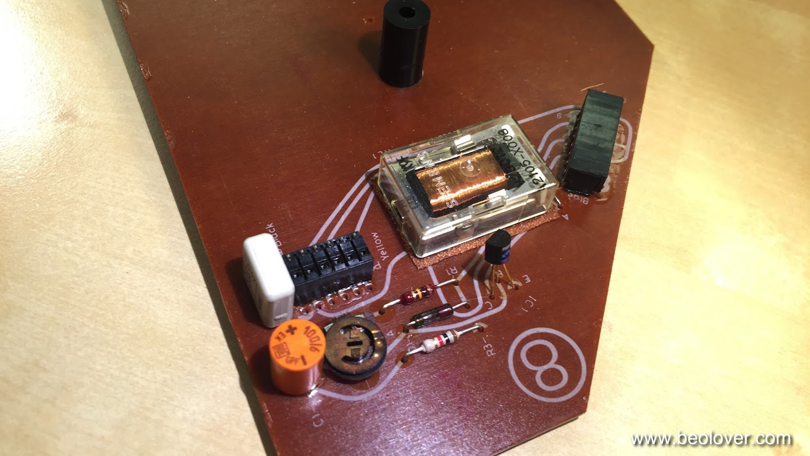
I like to replace the output relay, since they often get stuck on one or both channels as they age. Fortunately, it is the same relay that is used for switching the platter RPM and so my replacement relay boards fit here, too:
These parts are available to other enthusiasts, just send me an email.
This shows the relay and the capacitor replaced:
The red switch allows to connect the system and the signal grounds. This can help if there are hum issues due to improper connections within the amplifier or the cable (usually when RCA adapters are used that do not breakout the system ground).

Before I put the board back in, I also fixed the keypad. It had a loose key stop that caused one of the keys to pop up above the pad surface:
This shows the STOP key from the back with the loose stop:
I glued the stop back on and also reattached the loose pad strips on the sides:
This shows the end result of this repair:
Beautiful! On to adjusting the chassis and the platter.


Wednesday, February 24, 2016

Beogram 4002 (5513): Replacing the Incandescent Light Bulbs in the RPM Indicators with LEDs

After rebuilding the main PCB of the Beogram 4002 (5513) that I am rebuilding right now it was time to replace the incandescent light bulbs that provide the backlight for the RPM trimmer scales with LEDs. I like to do this to achieve better long term stability since LEDs have a much longer life expectancy than standard light bulbs. This picture shows the small circuit boards that I designed for the SMD LEDs. They are direct drop-in replacements for the bulbs:
These assemblies are available to other enthusiasts. This video shows how to install the LED boards.
This photo shows the RPM trimmer panel from the back with the original bulbs installed:
This shows the bulb covers removed:
and after installation of the LED boards:
And with covers back on:
On to repairing the keypad and rebuilding PCB #8 that sits underneath.