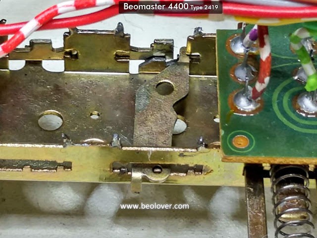
Here is the power on/off switch again as found in the Beomaster.
I definitely don't want to disturb the main PCB and the transistors on the heatsinks again just to change out the power on/off switch. You can loosen the front part of the Beomaster 4400 frame and extend it forward to get to the switch assembly and eventually the power on/off switch.
The other side of the Beomaster shows what I am talking about regarding access to the switch.
I have outlined the power on/off switch and Power On lamp for reference.
I had taken the front panel of the Beomaster 4400 earlier when doing the capacitor replacement but I didn't go into the front panel itself other than remove the slider controls for cleaning.
This time I need to be able to pull the front panel far enough away from the rest of the Beomaster so I can access the power on/off switch.
Starting with the front panel itself, I had to disassemble the front panel from the left and right Beomaster side rails. There are two screws for each side.
After that I am able to start pulling the front panel forward but it still has a long way to go. There are some wires that limit the travel as well as the front panel screws that attach to the transformer and reservoir capacitor brackets.
This picture shows the front panel pulled away slightly but still restricted.
I decided to desolder and get the solid blue and striped blue/white wires out of the way next.
Now the power on/off switch mounts can be seen.
There are four mounting tabs holding the switch to the switch rail assembly. The tabs are small and must be carefully bent to free the switch for removal. I still felt I didn't have enough operating room to remove the switch.
I really needed to pull off the front panel to access everything I needed to get to.
I removed the three screws that mount the switching rail assembly to the front panel.
I removed the headphone jack assembly
I removed the screws from the brackets for the FM Strength Meter, FM Tuning Dial and the FM Presets.
That left the FM Stereo LED still in the front panel. I didn't want to risk damaging the LED assembly by trying to remove it so I desoldered its two connections and pulled the wires out of the small bundle they were in.
Now the front panel is removed and I can get down to business with the power on/off switch.
First I removed the metal pushbutton parts. Technically, the metal switch part of the assembly could be left intact but I wanted to go through everything.
The switch assembly can finally be removed from the switching rail assembly.
Opening up the switch assembly reveals how burned up the switch contacts were.
These switch components look pretty bad. No wonder the switch wasn't working.
Fortunately I don't have to attempt to get them into some sort of working order and risk future problems. These power on/off switch assemblies are a real ordeal to access so I want a good replacement switch.
Fortunately I have the spare power on/off switch from the parts unit. The contacts and actuators have all been cleaned, polished and ready for reassembly.
After placing the components back in place I sealed the seam of the switch assembly with some black hot glue. It will help secure the switch assembly and can be peeled off in the future if it is ever necessary to open the switch again.
Now to install the power on/off switch back on the switching rail. Here is a sequence of photos showing the reinstallation of the power on/off switch.
There we are. A working power on/off switch again. Now for the task of reassembling the Beomaster 4400 front panel again.


No comments:
Post a Comment
Comments and suggestions are welcome!