Featured Post

Beolover SyncDrive: DC Platter Motor Replacement for Beogram 4002 and 4004 (Type 551x and 552x)

Late Beogram 4002 and the 4004 (Types 551x and 552x), which have DC platter motors instead of the earlier synchronous AC motors usually suff...

Thursday, October 14, 2021

Beogram 8000: Adding Quick Connect Capability for the Workbench Beogram 8000 uC

Now that I have my Workbench Beogram 8000 up and going I restored and checked out some Beogram circuit boards.

Two Beogram 8000 boards turned out to be real trouble.
Their uC (microcomputer boards - PCB 2) were not functional and they had power supply issues. Perhaps the two problems are related.

In attempting to evaluate the faulty boards I decided to use another Beogram 8000 board to check out the 1IC1 uC devices of the two boards. 

I tried swapping the PCB 2 Microcomputer assembly first but that did not result in a functional Beogram 8000.  

Next I tried swapping just the 1IC1 microcomputer IC.  I also tried two other uC devices.
That did not work either...even when installing the devices in a supposedly working PCB 2 assembly.
I know from working on a lot of these Beogram 800x turntables that the uC devices are pretty durable and it is quite unusual for them to be faulty.  So to have three bad uC devices didn't seem likely.  I needed to do some more testing of those ICs.

Changing the 40-pin uC devices is time consuming. You have to be very careful with them (protect against ESD) and installing them in another 40-pin IC socket is not all that fun.

What I really needed was a (easy) way to install them in my Workbench Beogram 8000.  In my known, working PCB 2 assembly.  The key word being easy.

I decided to modify my Workbench Beogram 8000's PCB 2 to be able to perform quick swapping of 1IC1.

I installed this 40-pin ZIF socket and socket receptacle assembly.


It required a little bit of Dremel surgery on the PCB 2 metal case but I decided that it would be worth it for the ease of swapping uC ICs.

Here is the original 1IC1 uC device re-installed in the new quick connect/disconnect socket.


Does it still work?


Yes...just as good as before.

Now I am ready to check out those suspected faulty 1IC1 devices from the other boards.

The first suspected 1IC1 device is from a board that the owner said the uC was doing strange things.
It would illuminate but sometimes show various combinations of LED segments.
Installing it in my Workbench BG8000 tester the suspect 1IC1 comes up in Standby mode.
That seemed good at first but nothing happens when I pressed the control panel buttons.  The uC appears frozen in that Standby mode.


I believe that confirms the uC IC from that board is indeed bad.

My other two 1IC1 devices however, tested good.
Here is one that I had already jumped the gun and marked as faulty.
Installed in the Workbench BG8000 it performs perfectly.


I feel good about my quick connect/disconnect socket for this Workbench Beogram.
I can see adding a couple of these sockets to one of my Workbench Beomaster 8000 uC boards.

Beogram 4004 (5526): A New Arrival from Southern Florida

A while ago I received a Beogram 4004 (5526) from a customer in Southern Florida. The unit was hand delivered. I extracted it from the packing peanuts (not my favorite packing material!...;-) and had a look. This post gives a first assessment of this Beogram before I will go about restoring it.

Once I had it out of the packaging,

it immediately became clear that the hood hinges are cracked. One decided to give out when I opened the hood, and a piece of plastic dislocated:

Unfortunately, this is a frequent issue with Beogram 400x hoods. It happens due to the high stress in this area, while the plexiglass is weakened by the presence of holes for bolting on the hood hinge. I carefully removed the hood and had a look at the other side, and a fine hairline crack is already visible, there, too. So this hood needs to be fixed on both sides.

Under the hood I found an unsecured MMC 20EN cartridge. Miraculously, the cantilever was still present and appears not to be bent much. We will see if this cartridge still can be used for playing records after this ordeal.

Other than the hood, this Beogram is in a pretty nice cosmetic condition. The aluminum panels are fairly pristine
and even the keypad only shows minor use patterns:
Unfortunately, the clear coat on these keypads does not like much being in contact with the acids and fats present on human skin, and so wear patterns occur depending on how much the deck has been used. On this Beogram they are only visible under certain light and view angles, so that is pretty good!

The plinth is also quite nice. The corners are almost pristine on both sides:

A look under the panels revealed that this Beogram seems to be unmodified and in its original condition (original condition is the best starting point for restorations):
After this inspection I plugged the deck in and pressed START. It creakingly came alive and displayed a shrieking platter motor. It proceeded to move to the LP setdown point and activated the solenoid. All very good life signs, indicating that the restoration should be straight forward.
 

Monday, October 11, 2021

Beogram 4002 551x: Exciting!! Replica DC Motor Bearing Prototypes from Beoparts Successfully Tested

I had received a second set of Beogram 4002 platter motor/main PCB and RPM panel for restoration from a customer in the Netherlands. As usual I started with the motor:

I took it apart to extract the bearings.
Usually, I would have now shown a picture of the bearings infusing with oil under vacuum. But this motor restoration is special! I recently received a set of custom made new Oilite bearings for these DC motors from www.beoparts-shop.com for testing. This shows the original bearings (top) in comparison with the new ones:
Exciting!! I installed them and reassembled the motor. 
The next step was to rebuild the main PCB. I replaced all electrolytic capacitors, the RPM relay, RPM trimmers and I installed a new high-gain transistor for TR3. This shows the board after restoration:
Then I replaced the incandescent bulbs with LED assemblies in the RPM panel:
And then it was time for testing everything in one of my Beogram 4002s. The first step was to adjust the TR3 bias properly with the 5M precision trimmer that I install as a replacement for the fixed value R26. First it needs to be installed on the solder side, so one can adjust the collector voltage to 4V while everything is plugged together:
Then it can be moved to the component side:
The next step was to measure the sensor response. This shows the oscilloscope trace I measured:
Each dip corresponds to a black platter rib passing by.
Once proper sensor operation was established I finally got to test the performance of the new bearings with a 24 hrs RPM stability test using the BeoloverRPM device:
And this is the curve I measured:
I would say this is an excellent result, as good as it gets with Beogram DC platter motors. This demonstrates that the new beoparts replacement bearings work as well as re-infused original bearings. A great simplification of the restoration process!


Sunday, October 10, 2021

Beogram 8000: Using the Workbench Beogram 8000 to Test a Speed Sensor Assembly

Now that the Workbench Beogram 8000 test setup has a three-pin connector in the platter drive harness for swapping speed sensor assemblies I can give that a try.

Here is the Workbench Beogram 8000 speed sensor assembly being swapped out with another assembly sent to me for testing.


The speed sensor assembly test candidate was taken out of its P4 wire harness and still has its P4 contacts. The owner should be able to re-insert them when I send back the tested speed sensor assembly.

I ended up making an adapter harness that would plug into my Workbench BG8000 3-pin test connector on one end and has mini-grabber probes on the other end.

In this case the mini-grabbers attach to the wires from the speed sensor assembly being tested.


Exercising the Beogram 8000 Play function with an empty platter I observed the Beogram search for a record while changing from 33.33 RPM to 45 RPM (as expected).  The speeds locked in easily so I think it is fair to say this speed sensor assembly is good.


I was curious as to how this other speed sensor assembly looks compared to the speed sensor that belongs to the Workbench Beogram 8000 turntable.

For that check I re-installed my Workbench BG8000 main board assembly.  That is because it is wired with probes for the sensors. I wanted to use my oscilloscope to capture a picture of the Beogram 8000 speed sensor assemblies at work and see how they compare.

My four probes for this test are -
1. Position Sensor 1
2. Position Sensor 2
3. The speed sensor LDR signal as it comes from the 1P4-7 connector
4. The speed sensor signal as it passes through the 1IC1 op-amp.

Here is a picture of the oscilloscope measurements I made.
I have one image for each sensor assembly at 33.33 RPM and 45 RPM...so a total of four pictures.
I arranged them together on one image so I can align the images to compare the speeds.


Not really surprising, the two sensor measurements do look different (because they are two different light sensitive devices).  However, even thought the signals do look different you can see that the period of the two speed sensor devices is the same (corresponding to 45 RPM and 33.33 RPM).

It is interesting that my Workbench turntable's sensor assembly operates at a 50% duty cycle while the test sensor assembly is less (maybe 35 to 40 percent ?).
That is another measurement I will start making on these Beogram 800x turntable restorations so I can compare them from turntable to turntable.

With both sensor assemblies this Beogarm 8000 was able to lock in the correct platter speed. 
I am declaring this speed sensor assembly sent for evaluation is good.

Saturday, October 9, 2021

Beogram 8000: Adding Speed Sensor Swapping Capability to Workbench Beogram

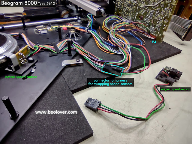
This is a quick update to show the addition of a new harness connector so the speed sensor assembly on the Workbench Beogram 8000 turntable can easily be changed.

In the previous post I described how the speed sensor assembly changed in Beogram 8000 turntables so for this Workbench Beogram 8000 to be useful in testing components it needs to be able to change the speed sensor assembly according to what type of main board is being connected. More detail on the Beogram 8000 speed sensor change is described by Beolover on this blog post.

There were a couple things standing in the way that prevent easy swapping of the Beogram 8000 speed sensor assembly.

The first problem is the speed sensor assembly is secured in place by two star lock washers. Those are the press to fit metal washers that secure to a mounting post. That type of washer is not meant to be repeatedly removed and refitted. They are designed to be used once. Not very convenient for a workshop test unit where the speed sensor assembly may be swapped out several times.

I decided in this case that since this is a test environment for the Beogram 8000 it was okay to secure the speed sensor assembly to the mounting posts with rubber grommets. They wouldn't be good for a long term installation but in this case they work quite well.


The second problem is the wiring of the sensor assembly from its harness to the main PCB.
The speed sensor is part of the platter drive harness that connects to the P4 connector of PCB 1.
It wouldn't be convenient to require changing out the whole harness just to change the speed sensor assembly.  It would also be a pain to de-solder and re-solder the three wires for the speed sensor each time.

The best thing would be to install a three pin connector just for the speed connector which is what I did.


The wiring for the speed sensor assembly easily connects and disconnect from the harness now.

Caution: Never operate the Beogram 8000 (or 8002) with only the hub attached. The black sub-platter is actually the rotor on these turntables so without it in place the Beogram control circuit will think it needs to keep driving the platter.  That will usually blow a fuse in the transformer. The sub-platter/rotor must be in place if attempting to operate the Beogram. 
Optionally you can disconnect the P4 connector from PCB 1 so all of the platter drive components are not connected.

A quick test to make sure everything still works with the test connector in place shows that the Beogram 8000 control circuit can still regulate the platter speed perfectly.


This modification to the Workbench Beogram 8000 allows me to easily configure the speed sensor according to the type of PCB 1 I am testing but what if I am trying to test out a different speed sensor assembly?

For that case I need to make a little adapter harness that allows for a speed sensor assembly test subject to connect its three wires (that I will assume will be loose) to a connector that will mate with my platter motor harness.

I think I will make the end of the adapter for the loose wires be one of those screw to tighten type of connectors.

That will have to be in the next post.

Friday, October 8, 2021

Beogram 8000: Utilizing the Workshop Beogram 8000 to Test a Board

It is time to put the Workshop Beogram 8000 to work.

I received some Beogram 8000 main boards (with their microcomputer boards attached) for testing and this post will show an easy use of the Workshop Beogram 8000. 

That is to do a restoration on the main circuit board and the microcomputer board then check that it works.
Since my Workbench Beogram 8000 is fully tested and working, swapping out the main PCB should result in the Beogram still fully functional...if the restoration is all good :-).

First though...A bit of caution regarding board swapping on a Beogram 8000.
Anyone that has worked on a Beogram 8000 will have noticed that there seems to be a lot of modification work on the electronics of these units. As a comparison, the Beogram 8002 electronics typically have no modifications.  My guess is that with the Beogram 8000 being a totally new design (especially technology-wise) from the previous Beogram 4002/4004 tangential arm turntables there were a lot of post-production hiccups that had to be addressed with service bulletins and mod kits.
One such modification was when B&O changed the speed sensor assembly in the Beogram 8000.
Beolover has a really good explanation of this issue as he ran into it in this 2020 blog post.

The important thing to take away from that is DO NOT put a Beogram 8000 main board that has the circuit modification for the newer speed sensor into a Beogram 8000 that is using the older type speed sensor assembly.  The reason being is that the newer circuit board is expecting the resistor between +15V and the speed sensor light source to be on the speed sensor assembly.  The older speed sensor assemblies DO NOT have a resistor there. They expect the resistor (R46) to be on the main board.
The result will be damaging (blowing) the speed sensor light source if this pairing is done.

Here is a photo of the two types of speed sensors.


You can see in the photo that the newer speed sensor has the addition of a small board with two resistors moved from the main PCB.

These next two photos show a board configured for the original speed sensor assembly and one configured for the new speed sensor assembly.


In my case of restoring this first board that was sent to me I don't have to be concerned about a conflict with the speed sensor assembly as my Workbench Beogram 8000 currently is fitted with the newer type speed sensor and the board sent for restoration is designed for the newer type speed sensor. 

Here is the current speed sensor assembly on the Workbench Beogram 8000.


To make the Workbench Beogram 8000 capable of testing both configurations of the main boards I will need to make a modification of my own to this test setup so I can quickly and easily change speed sensors. 

But first I will finish this first Beogram 8000 board set.

Here are the "before" photos.

The electrolytic capacitors will all be replaced. Board connector mounting points will all be re-soldered.


In the case of the small microcomputer board I removed the microcomputer IC so I have more room to work on the C28 capacitor and also to upgrade the 40-pin IC socket for the microcomputer IC.


Here is the board ready to begin work on.
As usual I pulled the mounting base off the large 2200uF capacitor so I can re-use it on the replacement capacitor.


I like to start with the microcomputer board assembly and get that part out of the way.
Here is the microcomputer IC back in place (in its new socket) and the new C28 capacitor.


The rest is just selecting and fitting capacitors and soldering.
Here is the board set completed and ready to install in the Workbench Beogram 8000.


Hooking up the transformer, connectors, control panel then plugging the Beogram in brings up the reassuring Standby dot LED that things are going good.


I pressed the Play button with the platter empty and observed the Beogram search for a record and automatically switch platter speeds.  Not finding a record, it returned home and stopped.


After that initial test I verified the power supply voltages on the board. They were all good.
As a final check I put on a record and checked out the record play handling.
Initial set down and drive through the lead-in groove was perfect.
So was the run-out groove and end-stop detection.
I also tested the Pause memory function and it worked correctly.
That is where you press Pause while playing a record. Leaving the Beogram with a record on the platter in the Pause mode for a few seconds will cause the Beogram microcomputer to think you stepped away for a bit. The Beogram will return the tonearm assembly to home and go into Standby mode.
When you press Play again the Beogram will return the tonearm to the spot you paused the previous play and resume from there.  Quite a nice feature.

I believe this board set is complete and ready to send back to its owner.

The next set is one with the circuit for the original type speed sensor assembly so I will need to change that sensor assembly for that project.

Wednesday, October 6, 2021

Beogram 8000: Workshop Test Unit

Recently a couple of Beogram 8000 owners sent me their circuit boards for evaluation. They are DIY type owners that needed some help with the electronics area of the restoration. It is much easier to work on the electronics portion of a restoration when you have good, working units to compare to.

This is the case with my Workshop Beogram 8000 turntable.


The parts shown above have gone through my typical Beogram 8000 restoration steps.
Everything on this turntable is fully working but will remain (for now) outside of its cabinet.
With everything open and accessible I can easily swap parts and connect measurement equipment to signals I need to measure.

For the main board I have now added the main Beogram 8000 signals I like to check: position sensors, tracking sensor, speed sensor, record detection sensor and the two servo motor control lines (forward and reverse).


I also recorded some measurements of those signals for key operations of the Beogram.

This picture shows the oscilloscope measurement when the Beogram 8000 Play button is pressed and there is no record on the platter.
For this mode of operation I looked at the two position sensors (of the tangential arm movement), the platter speed sensor and the arm detection sensor.

The activity begins as the platter starts to turn and the tonearm assembly moves towards the platter to search for a record to play.

Pulses on the Record Detect Sensor indicate the platter is empty.  
The pulses on the speed sensor show the turntable locked in at 33.33 RPM.
The two position sensor signals show a constant speed during the scanning for a record.

Those signals are as expected and indicate a healthy working Beogram 8000.
Here are some oscilloscope signals of the Beogram starting record play of a record on the platter.
I swapped out the Record Detection Sensor signal with the Servo Motor Forward signal.
The Position Sensor 2 signal was swapped out with the Beogram 8000 Tracking Sensor.
The Platter Speed Sensor signal was swapped with the Servo Motor Reverse signal.

The first picture shows the activity after Play is pressed to where the tonearm sets down on the record and accelerates through the lead-in groove.
Note the slow down of the servo motor right before the set down point.


Here is a picture of the activity during typical record play.
You can see how activity on the Tracking Sensor relates to forward movement on the Servo Motor Forward signal.


This last oscilloscope picture shows those same signals at the end of a record when the Beogram 8000 reaches the run-out groove of the record and the end-stop logic instructs the Beogram to stop play and fast scan in reverse back home.


With this tested and working Beogram 8000 I will now swap out some problem electronic parts and trouble-shoot their issues.