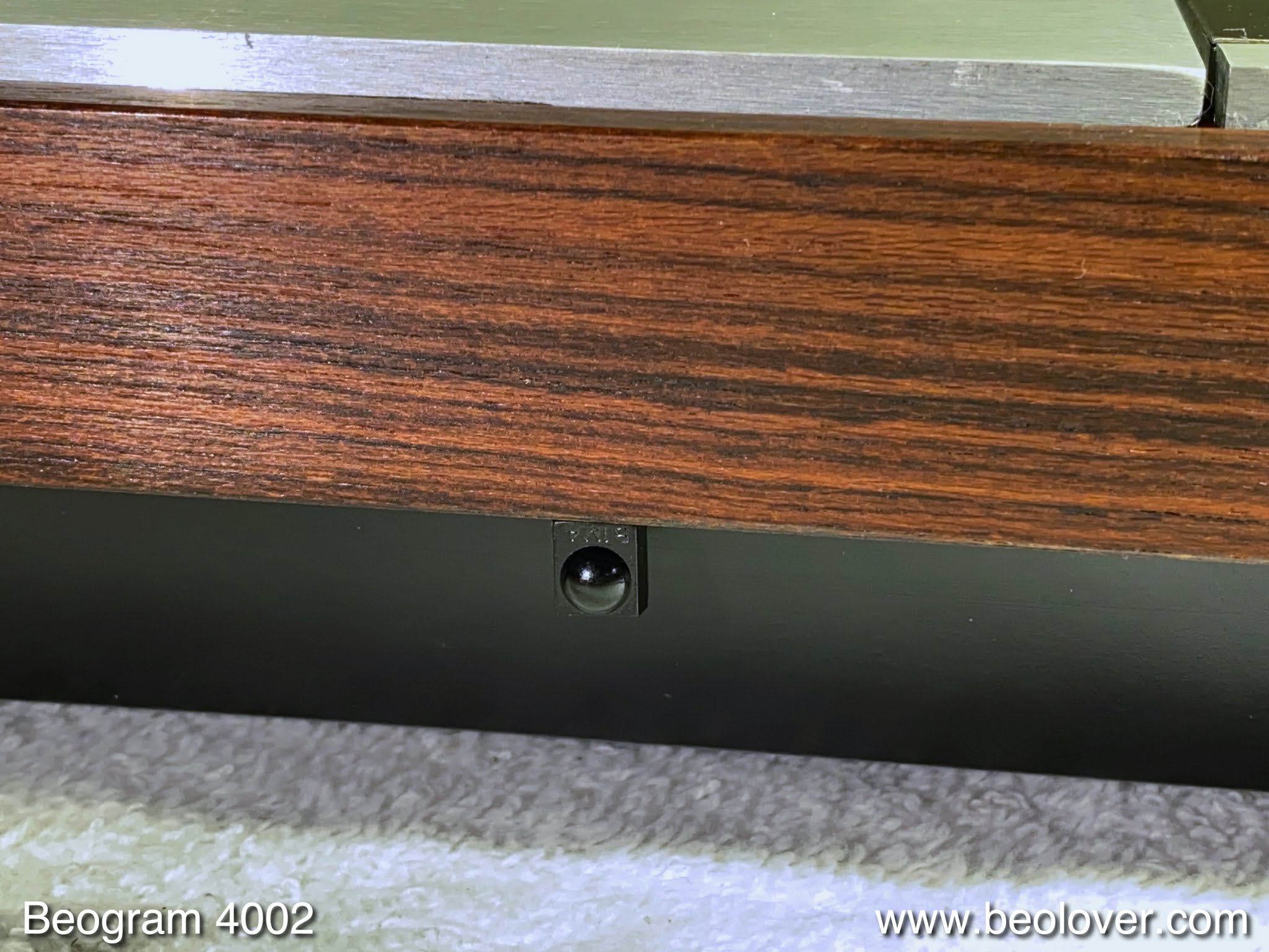
I recently started working on a Beogram 4002 (Type 5513) that was brought on US ebay by an Australian customer. It arrived in pretty rough condition:
My original assessment is posted
here.
This post describes the restoration of the unit (except the hood, which will be the subject of another post).
As usual, I started with the DC platter motor since the oil infusion of the bearings can take a few days. This shows the motor as extracted:
I took it apart to get to the bearings:
The bearings are the two small donuts on the black pad upfront. I immersed them in motor oil and pulled a vacuum. Immediately, strong bubbling started, indicative of air being drawn from the empty pores in the Oilite bearing material:
This escaping air creates room for fresh oil to penetrate into the bearing. While this process was going on I focused on the rest of the deck. First I restored the arm lowering mechanism. It is often impeded by hardened lubricants. This shows it as installed:
I took the moving parts out
and cleaned and re-lubricated them:
After re-installing them, I took out the sensor arm assembly. This shows it from the back:
I removed the damper to arm linkage and re-lubricated the pivot point:
While I worked on it I realized that the double-sided tape that holds the arm lowering limit 'skid plate' (no, this is not a Jeep!...;-) in place had weakened:
I removed the tape and epoxied it back to the arm base after re-installing the arm assembly:
While working on the carriage, I also replaced the light bulb that illuminates the tracking sensor with a LED based setup. This shows the original lamp housing in place:
And removed, revealing the aperture that is responsible for the tracking feedback:
This shows the original bulb and the LED based Beolover replacement:
I bolted the replacement in place and soldered the leads to the PCB on the carriage:
The final act to restore the carriage mechanism was to replace the cracking-prone carriage pulley
with a precision turned aluminum part and a new belt:
The next step was to focus on rebuilding the electronics. This shows the main board in its original condition:
I replaced all the electrolytic capacitors, the platter sensor transistor, and the RPM trimmers and the RPM relay with modern parts:
This shows the RPM section with the new encapsulated relay and 25-turn trimmers for precise and stable RPM adjustment:
Then I focused on the output board:
There I replaced the output grounding relay and the capacitor that defines its time constant (to delay the relay action until after the needle hits the grooves). I also installed a switch with which one can connect system and signal grounds in case there is a hum issue (the red switch in front of the black cable jack):
Another important item to replace is the main reservoir capacitor that stabilizes the power rail. It is often out of spec and/or leaking:
This 4002 was equipped with a double capacitance unit to accommodate a potential later 4-channel CD-4 upgrade, and so I installed my two single capacitor replacement assembly. These double caps are no longer available. The larger capacitor (4700uF) is for the main PCB, while the smaller 1000uF unit is for the CD-4 board if it ever gets installed. To make sure the 1000uF cap discharges properly after unplugging the deck, I usually install a 20k bleeder resistor between the CD-4 power rail and GND:

After completing the boards I replaced the remaining incandescent bulbs. First came the bulb in the sensor arm, which I replaced with a flex-PCB based drop-in replacement holding a warm-white LED and a bypass resistor to ramp up the current to the level of a light bulb. This is necessary to ensure that the record detection circuit recognizes the LED as a 'proper light bulb' and so enables arm lowering. This is a safety feature that prevents accidental arm lowering if the bulb is burned out. This shows the original bulb and the replacement assembly:
and with the bulb extracted:
and after installing:
Next were the light bulbs in the RPM panel. Unfortunately, this panel had a blemish:
So I replaced it with a substitute from a part unit that I had on the shelf. I removed the bulb covers
and replaced the bulbs with my LED boards:
This shows one of the boards in action:
On to more mechanical tasks: The later 4002s were outfitted with softer but less-lasting transport lock bushings. These often crumble during shipping. The ones I found in this deck were still intact but poking one of them with a screw driver revealed that they were also close to end of their lifetime.
So I decided to replace them preventatively. I removed the entire floating chassis for this task and vacuumed the enclosure:
This shows the 3D printed replacement bushings:
I separated and installed them. Each bushing is made up of two parts, which makes installation very simple. Just push one half in from the bottom,
and one from the top:
And that is it!
I put the locks back together:
After reinstalling the floating chassis it was time to make some adjustments. This shows the adjustment of the sensor arm transistor bias with the 5MOhm 25-turn trimmer that I usually install for this purpose. With this trimmer it is easy to get the collector of the transistor to the prescribed 4V:
After the adjustment I moved the trimmer to the component side of the board, where it neatly fits into the space vacated by the original fixed 1MOhm biasing resistor:
While I did all the work shown above the bearings completed their oil infusion process and I extracted them from the oil:
I put the motor back together and installed it in the Beogram for an RPM stability test with the BeoloverRPM device:
It allows logging the RPM for extended periods of time in 10s intervals. A great way to check if there are intermittent RPM fluctuations, which are notoriously difficult to detect by listening to records. This is the curve I measured after about 24 hrs:
This is pretty much as good as it gets with DC platter motors.
On to more adjustments: Before calibrating the tracking weight scale, I replaced the flimsy circlip that holds the adjustment screw of the arm counterweight in place
with a M3 nut and a washer:
This allows fixing the counterweight firmly in place. That way the calibration will survive the shipping process. After that was done, I calibrated the weight dial using a digital scale:
Then I adjusted the arm lowering limit to ensure that the needle was able to go below the record, but not far enough to hit the platter ribs in case the record detection mechanism malfunctions and the arm is lowered without a record present:
Then I adjusted the tracking feedback. The trimmer (blue box) on the tracking sensor LED, which allows adjusting the light intensity from the LED is very helpful for fine-tuning the feedback:
After these adjustments I spend a couple hours adjusting/leveling the floating chassis and the arms, as well as rectifying the badly out of adjustment pins that hold the aluminum plates in their correct positions (unfortunately, this Beogram had been 'messed with' by prior owners, and so everything was throughly out of alignment).
And finally, it was time to think about playing a first record. But before doing that I still needed to replace the badly corroded RCA plugs:
My customer told me that this deck will be used together with a Beomaster 6000 4-Channel unit (excellent choice!!), which made it necessary converting it back to a DIN plug. I extracted an original DIN output cable from a donor unit. In order to get it in and out of the enclosure one has to liberate the contact terminals from the Molex style plug shell:
This shows the (of course) corroded DIN5 on that cable
Actually this plug is a 'convertible' DIN7 with pins 1 and 7 removed, since this cable came from a Beogram 4004, which has a simple early form of Beolink in stalled on the two additional pins. This cable was perfect for this 4002 since the cable has two additional leads in it, which I used used for the back channel pins if this deck were ever upgraded with a CD-4 board (the red and white leads are the standard main/front channels and the yellow and blue are on the back channel positions (not used on the current output board):
This shows the nice new DIN5 with gold plated terminals:
The final task was to replace the worn keypad with a restored one that I had on the shelf and cleaning the aluminum panels. And then it was finally time to give this deck a first spin. I selected one of my favorite Cal Tjader albums:
"Warm Wave" from 1964. On this album he teamed up with
Claus Ogerman, who arranged and conducted the orchestra. This collaboration yielded a sublimely smooth latin jazz record, perfect for long afternoons of Beogram restorations! Of course, this album was thoroughly cleaned on a
CleanerVinyl ProXL ultrasonic record cleaning system fitted to a UC-3360 multi-frequency cleaner. This process restored this album to a like-new condition with minimal pops and clicks and quiet black space.
This shows this lovely album playing on the now pristine looking Beogram 4002:
Beolovely! The remaining task is restoring the badly scratched and dirty hood. Let's see what a couple hours of workout in the garage can do! I hope I can bring this hood back to a near-pristine condition! Stay tuned!