Featured Post

Beolover SyncDrive: DC Platter Motor Replacement for Beogram 4002 and 4004 (Type 551x and 552x)

Late Beogram 4002 and the 4004 (Types 551x and 552x), which have DC platter motors instead of the earlier synchronous AC motors usually suff...

Thursday, December 27, 2018

Beogram 4004 Type 5526: Recapping the boards on the second Beogram 4004 from Texas

I removed all of the components that were necessary from the Beogram cabinet to clean out all of the debris from the old transport bushings.


The cabinet is now ready as I work on the individual components.

I decided to tackle the recapping of the two circuit boards first.
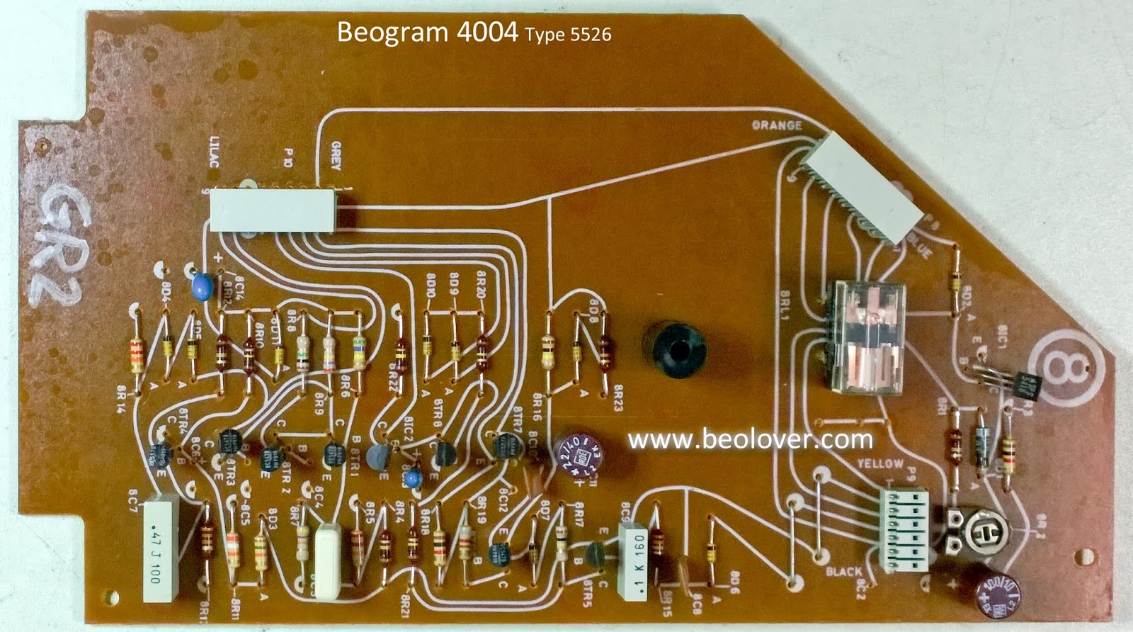
Here is the main (controller) board before the recapping. Note that the RPM relay on this Beogram controller board is the National type of relay. It has a different footprint than the Siemens relay used on the first Beogram 4004 I restored. Beolover's replacement relay assembly comes in both sizes so that isn't a problem. You do need to check that before ordering a replacement relay for your project.


Here is the output board. It also has the National type relay. So far I have found that whichever type of relay (Siemens or National) is used it will be on both boards.


On the recapping of the controller board I replaced all of the electrolytic capacitors and tantalum capacitors with 105°C, Japanese electrolytic capacitors or WIMA MKS capacitors. The two trimmers for the 33⅓ RPM and 45 RPM platter speed calibration were changed to sealed, multiturn type trimmers. I also changed capacitor 1C10 from the original 0.33uF to 10uF. The reason for that is because the stability testing on the DC platter motor after Beolover's restoration process showed that the 10uF value provides more stable speed results.

Here is the recapped controller board.


On the output board I also replaced the electrolytic and tantalum capacitors with 105°C Japanese electrolytic capacitors and WIMA MKS capacitors. The muting relay was traded out for the Beolover replacement relay and our usual grounding switch was installed. The grounding switch provides more options for the phono cable connection to non-B&O preamplifiers. In most cases it eliminates the need for the extra, external grounding wire from the Beogram to the preamplifier.


Both boards are ready to use.

Wednesday, December 26, 2018

Beogram 4004 Type 5526: Second Beogram 4004 from Texas

When I started the last Beogram 4004 project I mentioned that it was one of two from the same owner. Both units were purchased new back in the late 70's. The first unit (serial number 1750052) is a little older than the second one (serial number 2030024). The second Beogram also has the lighter, teak trim while the first one has the more common rosewood trim. Both look really nice.


Like the first unit this one has been extremely well taken care of. The only thing that stopped it from working is aging parts that this restoration will fix.

I always remove the dust cover and safely store it away when I work on Beogram turntables. It is easier to work on the turntable restoration without having to worry about accidentally bumping the dust cover.

The platter is pretty well centered in the cabinet. I like seeing that.


Inside the Beogram has the expected debris from the deteriorated transport bushings. Beolover 3D printed replacements will take care of that (after I clean the loose pieces up).


The platter motor that is usually in the upper left corner of the picture (above) was already removed and sent to Beolover for restoration when the motor from the first unit was done. I will reinstall it after I work on the other components in the cabinet.

The tonearm and fixed arm assembly looks to be in excellent shape and like the first Beogram 4004 unit, still at the factory settings.


The tangential arm assembly drive motor and pulley look like they need some work. That was expected. All of the plastic pulley's I have come across have small cracks where the pulley mounts to the spindle. The motor assembly doesn't look like it is centered in its case...by looking at its pulley.
I will restore these the way I did on the first Beogram.


Here is a look at the main board (the controller board) and the output/remote control board. They will have their electrolytic and tantalum capacitors replaced. The controller board will also get a new RPM selection relay and two new RPM speed trimmers. The output board will get a new relay and a grounding switch will be added (as we normally do on these turntables).

Note that this Beogram has the National type relays instead of the Siemens type relays. Beolover makes replacement relay modules for both types.


Finally, here is the Beogram 4004 at my typical restoration starting position. I will remove the floating chassis to clean and lubricate it. I will remove the suspension lockdown components to replace the bushings. I will also clean the empty cabinet of any debris from the old bushings.


Tuesday, December 25, 2018

Beogram 4004 Type 5526: Reassembly, Service Manual Checks and Record Play

Merry Christmas!

The Beogram 4004 turntable from Texas plays its first record since its restoration.


The original (and only) owner of this beautiful Beogram 4004 turntable was an avid jazz lover so as homage to him I felt the first record played on the restored turntable should be a jazz record. I am fond of the trumpet and I like Freddie Hubbard so there you go. The red vinyl reissue of Red Clay also makes for a cool photo.


Now to backtrack to how I got here.

In the previous post I had completed the electric work checks and I ran some functional tests of the Beogram's analog control system. Everything was working perfectly. Although the control panel button board didn't exhibit any problems this is a good time to clean the switch contacts.


The fixed contact looks really good while the contact that engages with it shows some tarnish. That is to be expected. I removed all of the fixed contacts so I could clean all of the surfaces with a fiberglass brush and coat the surfaces with Deoxit.


The next step was to reassembly the control board and get all of the loose pieces reinstalled in the Beogram cabinet for some service manual checks.


The first service manual adjustment was the turntable platter height. It turned out to just be an adjustment check as this turntable was still at its perfect adjustment set by the Bang & Olufsen factory. Pretty amazing when you think about this being 2018 and this Beogram was made in 1978.
Note that this adjustment is made with the platter belt removed.


It is worth mentioning that in some of the pictures the lighting shows there are finger-wear marks on the control buttons of this Beogram. That means this was a well used turntable. Even more remarkable at how pristine this Beogram is. It didn't just sit around for show.

I put the platter belt back on and performed the platter speed adjustments next. This Beogram had its DC platter motor restored by Beolover. Combined with new electrical components (capacitors and speed trimmers) in the controller board, the speed trimmers need to be dialed in to set the platter speeds correctly for 33⅓ and 45 RPM.


On the next service manual adjustments I removed the platter belt again to check the tonearm lowering limit, tonearm length, tracking force calibration and the record tracking.


Everything was right on except the tracking force. I had to recalibrate the tracking force knob but it was no problem.

The linear tracking sensor of the Beogram is checked and adjusted by manually rotating the platter with a test record while the tonearm is engaged for play. The revolutions of the platter are counted as you observe the tangential tracking motor advance the arm assembly. I haven't found a good way to document that with still photos so here pictures of the the post adjustment check. In this case, like most of the other adjustments, the tangential tracking was already perfect.

This tracking check with the platter belt back on checks that the tracking control system keeps the stylus centered with the tonearm as stylus moves in the test record grooves.


Satisfied that the Beogram is adjusted properly for record play I finished reassembling the Beogram cabinet. That involved the last adjustments which are mainly cosmetic. The floating chassis has to be adjusted so the platter is centered in the deck opening and the platter surface is even with the Beogram deck.


That brings us up to date with the first record play test.


Before reinstalling the Beogram 4004 dust cover I will test play the Beogram connected to one of my stereo systems for a few days to make sure I didn't miss anything and exercise all of the new parts.

Saturday, December 22, 2018

Beogram 4004 Type 5526: Finishing up the electrical work and testing the results

I left off the first of two Texas Beogram 4004 restorations with the main (controller) board and the output board recapped. There was another electrical task I wanted to complete before reinstalling and testing the results.

We like to (insist really) that the 33⅓ RPM and 45 RPM indicator lamps be replaced with Beolover LED replacement assemblies. The reason for that is those lamps are part of the platter speed control circuit and our speed stability testing shows these LED replacement modules provide a measurable improvement to the platter motor performance stability.

Here is the original RPM indicator module removed and the installation of the replacement Beolover RPM indicator assemblies.


All of the electrical pieces are ready so it is time to reassemble things back in the Beogram cabinet.

One of my earlier posts showed that the suspension locking bushings on this Beogram were deteriorated to the point of crumbling away. The next pictures show the installation of the Beolover 3D printed replacement bushings.


I am not fully reinstalling the circuit boards yet. Just connected up so I can test power and basic functionality of the electrical work.


It is very common for these Beogram 4002/4004 units to work electrically after the work on the boards. Since this Beogram 4004 is in such pristine condition I fully expected that to be the case here.
To my surprise there were a couple of problems. The On automatic scanning for a record did not work. Neither did the Off automatic return or did cueing up and down. The manual scanning worked and the platter motor worked.

Looking at the sensor lamps in the Beogram I could see that the fixed arm lamp was working along with the tracking sensor lamp. The new RPM indicator lamps worked but the carriage position lamp did not. I figured the burned out carriage position lamp was the problem.


I have had to replace these before so I grabbed my usual amber LED replacement part.
Here is the failed, original carriage position lamp.


...and here is the replacement.


The new lamp works as expected and I adjusted the voltage on the anode side per the service manual to +5VDC when a clear part of the position slide scale is between the lamp and sensor.
The signal at the anode side of the LED looks correct when the tonearm carriage moves across the sensor.


Unfortunately the auto scanning and cueing functions still fail.  That means there is some control function problem.

These Beogram 4002/4004 turntables from the seventies still look modern today. The way they operate will cause most unfamiliar observers to think this turntable is controlled by some computer chip of some kind. They would be wrong of course. The controller in this turntable is an analog control system. Optical sensors and microswitches feed the analog control circuits where transistor switches manage the logic. Pretty cool.

Looking at the circuit diagram for the start, stop and scanning I looked for where the fault could be.


The transistor switches I suspected are highlighted in red. 1TR12 and 1TR13 are supposed to latch for their respective forward (ON) and reverse (OFF) scanning. I desoldered and checked them with my transistor tester and they appeared to be good. I went ahead and tested 1TR11, 1TR14 and 1TR15. They also measured good. Next I tried 1TR8...also apparently good.

After a lot more probing and measuring I was at a loss to what the problem was. I finally decided that it had to be something involving those transistors or their connection. While the service manual says the transistors there are all BC237B transistors the board actually used BC547B transistors. I decided to go ahead and replace all six transistors...and the Beogram control logic started working correctly.

Interesting that the faulty transistor(s) measure good out of circuit but I have seen that before. It is something to keep in mind when diagnosing a problem.

Now I have a working Beogram 4004. I can move on to doing the service manual checks then play some records.