This post describes the tasks performed during the restoration of a Beogram 4002 (5513) that I received from a customer in Florida. My initial assessment of this unit is described here.
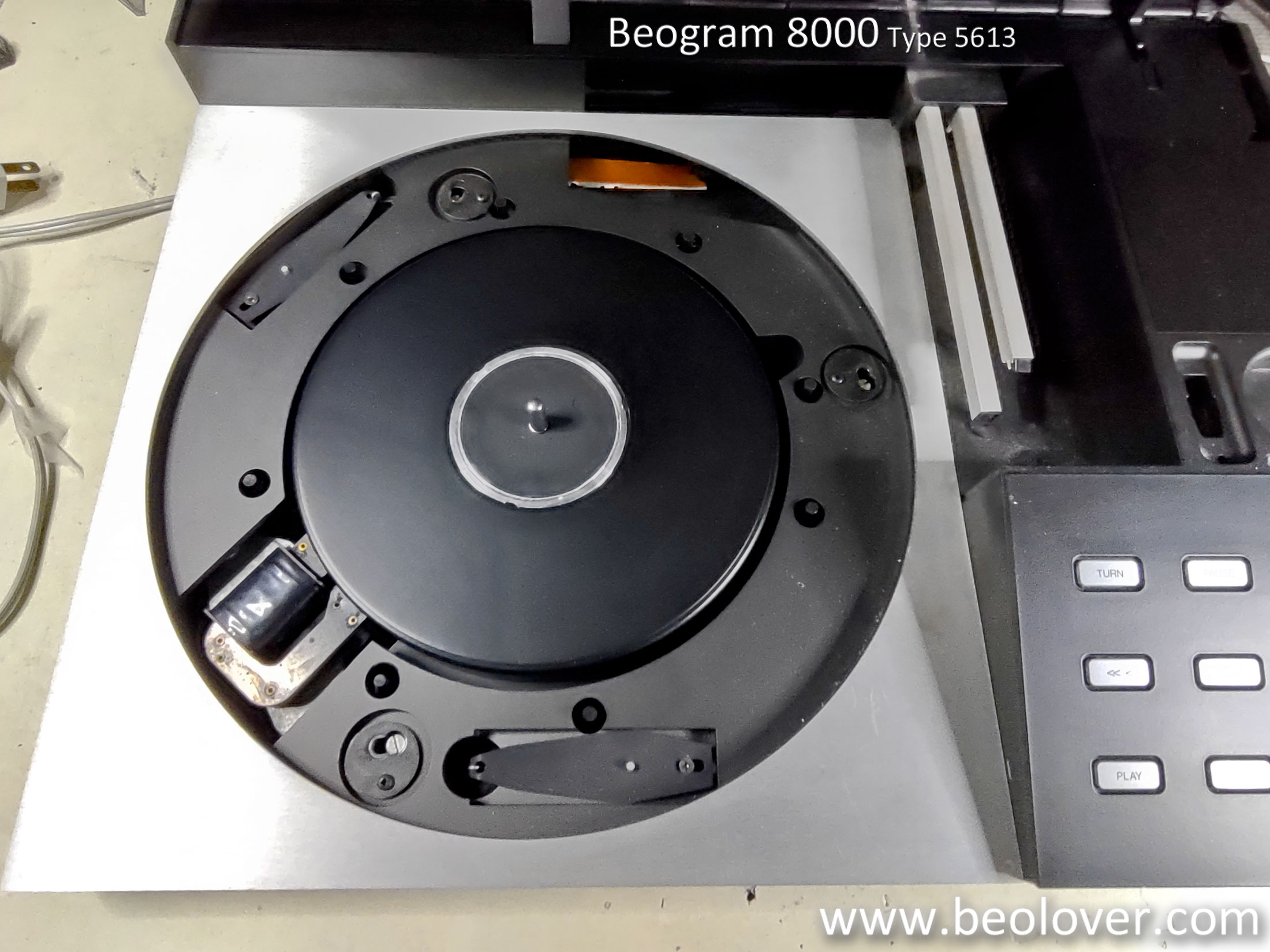
This shows the unit as received with the aluminum panels and platter removed:
As usual with DC platter motor Beograms I started with the motor. Most need their dry Oilite bearings replenished with oil, hence this procedure is a standard restoration task. This shows the motor after extraction:
I took it apart to get the bearings out. They are the two small donuts on the black pad upfront:
I put the bearings into my oil jar and pulled a vacuum. Immediately hungry bubbling started as the vacuum pulled the air out of the bearings to make room for fresh oil to diffuse into the material:
This process usually takes 2-4 days, so it was time to focus on the rest of the deck. The next step was removal and cleaning/re-lubrication of all the moving parts of the carriage and arm lowering mechanisms. This shows the assembled carriage with all the parts still in place:
I removed everything and also took the damper apart:
The parts went into the ultrasonic cleaner for a while.
I replaced the two power transistors that are mounted on the solder side of the main PCB, and then I removed the PCB itself for a thorough reworking:
This shows the 'RPM section' in its original condition:
I removed all electrolytic capacitors, replaced the power transistors of the H-Bridge, replaced the RPM relay and RPM trimmers (they are a frequent source of RPM stability trouble), and I also replaced the transistor (TR3) that amplifies the record sensor signal (it often looses some gain, causing record detection issues). This shows the refurbished board and the extracted components:
Then I removed the keypad and took the output PCB out:
On this board I usually replace the output relay and the capacitor that defines the time constant for its activation after arm lowering has been executed. I also installed a switch (red) that allows connecting signal and system grounds, which can be very helpful if there is a hum issue:
With the keypad out, it was a convenient moment to replace the light bulbs in the RPM adjustment panel. This shows the panel removed and upside down. This revealed that one of the bulb covers was missing:
This shows both bulbs still in place after removing the remaining cover:
Then I prepared the Beolover RPM LED boards for installation. They solder directly to the solder pads for the bulbs:
This shows the panel with the LEDs installed and the one cover back in place:
Since the LEDs only radiate 'forward' the covers are not so important, i.e. it does not really matter much that one of the covers went missing (they prevent light from the bulbs to shine though cracks between the aluminum covers around the keypad).
Before putting the carriage back together, I replaced the tracking sensor light bulb. This shows the original tracking sensor set-up:
I removed the bulb housing, which revealed the aperture that governs the tracking feedback:
I installed the Beolover tracking sensor LED assembly, which replaces the bulb housing plug-and-play.
The small white box on top is a trimmer that allows tuning the light intensity of the LED. This can be helpful to precisely adjust the tracking feedback.
The next step was the removal and re-lubrication of the linkage that connects the arm lowering damper with the arm itself. You can see the linkage on this photo protruding from its V-notch on the arm assembly:
To get to the linkage the sensor arm needs to be removed:
I removed the linkage (note that there is a small spring under the circlip, which likes to get lost if one is not careful):
I cleaned the pivot point from old lubricants and re-installed the sensor arm with the linkage. Then it was time to put the carriage assembly back to gather. This shows the now cleaned components:
These days I always install a new rubber gasket in the damper plunger, which reliably eliminates any arm lowering inconsistencies. It seems the original gaskets often have trouble sealing the air path inside the plunger properly:
This shows all the now shiny pieces back in place:
The last item on the carriage was replacing the original plastic pulley, which already showed a hairline crack:
This shows the machined aluminum replacement in place:
At this point most components had been removed from the enclosure, and so it was time to replace the, as usual, fragmented transport lock bushings:
Since this Beogram has the dual-power supply setup that prepared it for the installation of a CD-4 board, the floating chassis cannot be removed without unsoldering a wire. So I just placed it carefully on the rim of the enclosure after removing it:
It is important to vacuum out the enclosure after exchanging the bushings. Fragments of the old ones tend to distribute throughout the enclosure, and they can impair the free floating action of the chassis. Here you see some errant fragments:
This shows the Beolover replacement bushings:
They come in two parts, which makes installation very easy. Just insert one half from the bottom and the other from the top:
This shows one of the locks re-assembled:
On to the main capacitor. It is of the 'dual-capacitance' type, which are not made anymore:
This means one needs to replace it with two individual capacitors joined at their negative end. This shows the Beolover dual capacitance assembly:
The 20k resistor soldered across the smaller capacitor serves to bleed it after unplugging the Beogram. Without a CD-4 board installed this capacitor has basically no function, i.e. it can retain its charge for long times. A while back I damaged some components by accidentally touching the power lead that comes from this capacitor, so I thought it better to add the resistor, which will empty the capacitor within a few minutes.
At this point there was still one bulb left to be replaced with a LED assembly. This shows the sensor arm bulb removed from its compartment together with the Beolover LED assembly:
The assembly installs 'plug-and-play', i.e. it replaces the bulb without the need for further modification of the circuit:
This shows the LED in action:
With the board installed again, it was time to adjust the bias of TR3 to get the prescribed 4V at its collector. This is made possible by replacing the 1M bias resistor with a 5MOhm trimmer that allows a precise adjustment:
After this was done I moved the trimmer to the component side of the board and set out to measure the sensor response. This is a recommended procedure whenever one works on the record detection circuit. This shows the signal measured at the collector of TR3 with the platter rotating under the sensor. An impressive amplitude of more than 8V was achieved. Plenty for the detection of the absence of a record!:
While putting the keypad together I noticed that the RPM panel sockets were cracked:
All you need to do is to move the metal spring clips over to the new parts, which is very easy to do:
This shows one of the new parts installed:
Beolovely!
This restoration was nearing its end and so I looked into the output cable. Someone had replaced the nice original B&O DIN5 cable with a monstrous RCA cable, like they have become common in modern hifi setups. Here, unfortunately, the unwieldy cable impaired the motion of the carriage and also looked pretty messy:
I made an effort to save the board header that was still original. I pulled the contact terminals from the plastic shell, which is fairly easy with a small screwdriver for pushing the locking tabs down:
I cut the crimp ends off the terminals, and soldered them directly to the end of a new DIN5 jumper cable. I usually buy these cables from
Sounds Heavenly in the UK. Steve Marriott makes these cables and they are perfect as a quality replacement of the original B&O cable after removal of one of their DIN5 plugs. This shows the rescued header terminals soldered to the cable leads:
And after inserting into the plastic shell:
Since the 'monster RCA cable' was so thick, whoever did the conversion lost one of the two cable retainer pads since otherwise the cable would not have fit through the cable pathway designed into the Beogram enclosure. Since the new cable had again a more manageable diameter, I needed both of the pads. So I designed a 3D printable replacement:
This shows the re-assembled cable retainer in place:
This shows the plug plugged into the board header:
A view of the nice gold plated terminals of Steve's cable:
At this point the oil-infusion of the motor bearings had come to an end, indicated by a ceasing of the bubbling. I extracted the bearings from the oil:
and installed them back in the motor housing:
Then I re-assembled the motor and bolted it into the enclosure and put the platter on with a new belt. Then it was time for a 24 hrs test of the motor to assess its RPM stability with the BeoloverRPM device:
The BeoloverRPM allows logging the RPM in 10s intervals, which is great for spotting intermittent RPM variations. This shows the curve I measured after 24 hrs:
This is a pretty good curve for a DC motor Beogram. The slight choppiness is a sign of the motor bearings breaking in in their new orientations. I usually try to mount them in their original orientation, but slight variations from this position are unavoidable and cause the need for some runtime before the motor runs completely smooth again. At any rate these variations are so small that they could never be discerned while listening to a record. So it is all good in the motor department again!
At this point it was time to do the remaining adjustments. I first adjusted the platter tilt to be aligned perfectly with the arm movement across the platter. Then I adjusted the floating chassis to get a platter that is flush with the surrounding aluminum panels. After this was done I focused on the calibration of the tracking weight. The first step is always replacing the flimsy circlip that holds the screw in place that is used to adjust the counter weight with a M3 nut. That way I can fix the calibration in place in a way that it can withstand shipping/transport.
In this Beogram someone had already attempted to lock the calibration in place with some messily applied black paint:
I scraped the paint off and then put the nut in place:
Then I calibrated the tracking weight dial to be accurate around the 1.2g setting that most B&O cartridges need:
It is always recommended using a digital weight gauge instead of just believing the scale on the adjustment wheel. They are notorious for being a bit off.
After this was done, I adjusted the arm lowering limit to point that will protect the cantilever if the arm should ever be lowered onto a spinning empty platter (the only way this can happen is due to a circuit malfunction):
The final adjustment was the tracking feedback sensitivity:
And then it was finally time for a test spin! Since I have a bit of a Cal Trader phase right now, I selected the fourth release of the
Cal Trader Quartet from 1958 titled simply "Cal Tjader" (Fantasy 3253). It came in translucent red vinyl, which was a bit of a thing back then. My original release copy of this record still has a pretty decent sleeve, and the record mostly plays fairly well. It can be difficult to find vinyl of this kind of vintage since back then many turntables had pretty high tracking weight or coarse styluses, which can leave such records pretty 'crackly'.
Cleaning it ultrasonically with a
CleanerVinyl ProXL setup helped a lot to restore its original no-fuss mono sound, which is very appropriate for this type of music. Just listen to 'Our Blues' on Side One and you will know what I mean.
This gives an impression of this lovely album playing on this newly restored Beogram! Even the MMC 20E cartridge that came with it is still in a decent condition!:
Very nice! It always is very a happy moment for the Beolover when a Beogram 4002 has been restored to its original glory, performing like new and playing an iconic vinyl record! This deck will still receive a Beolover Commander remote control as well as a new reproduction hood! Stay tuned.