Featured Post

Beolover SyncDrive: DC Platter Motor Replacement for Beogram 4002 and 4004 (Type 551x and 552x)

Late Beogram 4002 and the 4004 (Types 551x and 552x), which have DC platter motors instead of the earlier synchronous AC motors usually suff...

Sunday, December 15, 2019

Beomaster 2400: Restoration Project for a Texas Owner

There is just barely enough time to get in one more vintage Bang & Olufsen restoration project for 2019.

This is another Beomaster 2400 restoration. I have had quite a few Beomaster 1900 and 2400 projects this year so why not another one.

Let's jump right in and evaluate the starting condition of this Beomaster.

Cosmetically it looks very nice.


Since it is in such nice shape I decided to power this unit up and see what its status is with regard to lights and touch control switches.


I was pleasantly surprised that all of the touch switches work and most of the lights do as well. The Treble indicator light is burned out apparently.

Now on to opening the Beomaster 2400 cabinet up to get to the circuit boards inside.
For this restoration project I will be doing the usual replacement of electrolytic & tantalum capacitors, the cleaning of the slider switches and any other repairs I run into as I check out the insides of this receiver.

First I remove the door and panel for the tone controls and FM channel tuning.


Second is the removal of the Beomaster 2400 bottom plate.


Note that the Phono DIN plug is the 7-pin type. That means this Beomaster has (or supports) the circuitry for (wired) remote control of a Beogram 4004.
That is desirable in this case because the owner has a fully restored Beogram 4004 ready to use with this receiver.


Now for the removal of the touch control panel.


The bass, treble and balance controls have indicator masks that are in excellent condition. I will have to look closer but all three slider controls appear to be fully intact.


This version of a Beomaster 2400 has different and newer board to board connectors.


Here is the main body of the Beomaster 2400 after I have removed all of the other components.


I don't like trying to de-solder and solder electrical components in between the frame pieces of the cabinet. I prefer to remove boards and components from a unit and work on them individually.
This Beomaster 2400 is now broken down to where I can start recapping the main board.
I like to start with the most difficult task first and get it out of the way.


Saturday, December 14, 2019

BeoGram CD X: Restoring the door motor

In the previous post about this BeoGram CD X unit I got it working again by reworking the board vias. While the CD X was playing CDs again its motorized door was struggling with opening and closing.

I ordered a new belt for the door motor and received it from Martin Olsen this week.

This post shows the opening back up of the CD X and changing out the belt motor plus checking capacitor 2801 (220uF, 10V) of the door's motor drive circuit. The capacitor is sometimes faulty.
I will also show the restored vias on the Servo board (PCB 04) as I promised in the first CD X post.
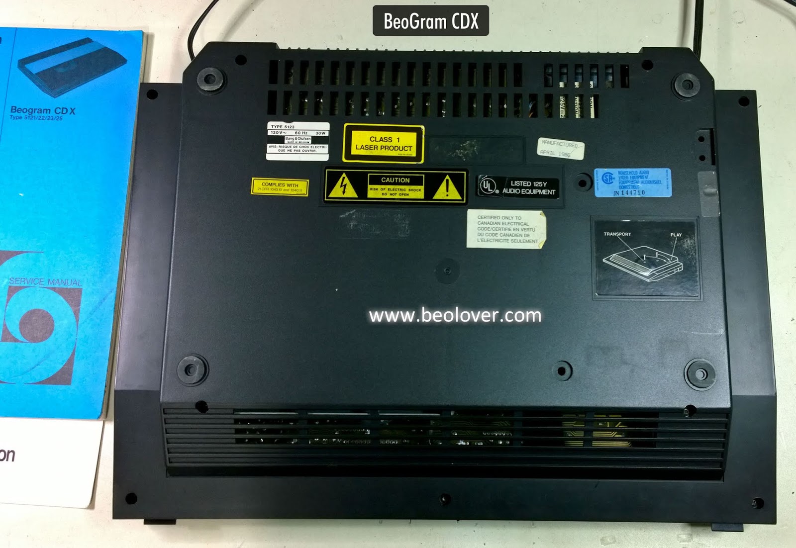
Here is the CD X with the bottom cover removed. You can see the door motor assembly on the left.


I removed the top cover from the main CD assembly to make easier work of the belt replacement.


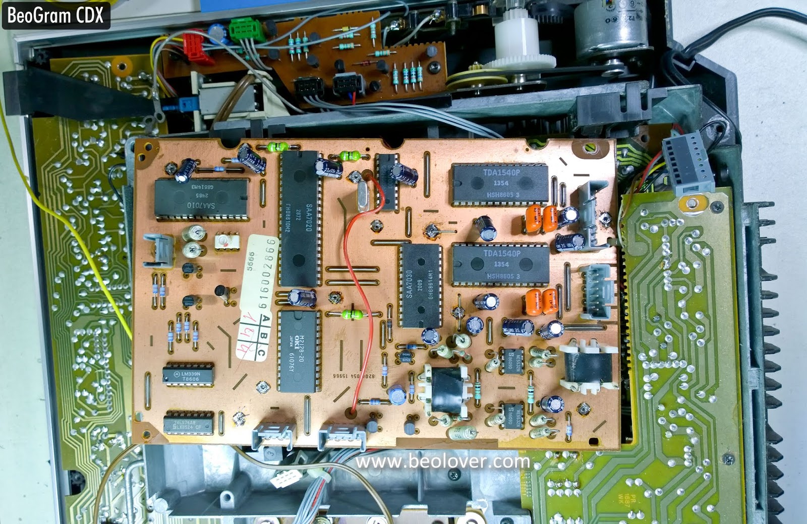
While the CD assembly is out I will take this time to show photos of the Servo board (PCB 04) I restored the vias on earlier.


Continuing with the CD X motor belt and capacitor 2801 replacement, this next picture shows the CD X top cover with the door motor assembly.


The door motor belt cannot be replaced without some more disassembly so the next few pictures illustrate taking the motor assembly apart to get at the belt.


To remove the gear blocking the extraction of the belt there is one of those pesky C-clips. Pesky because they are very easy to lose.


I had to loosen the two screws on one door switch assemblies to give enough clearance to remove the large, white, plastic gear. Finally the belt as accessible.


I installed the new belt and reassembled the motor assembly.


Now it is time for the 2801 capacitor.  I de-soldered and removed it. Sure enough the 220uF capacitor only measures 65uF.


Replacing it I can continue the reassembly of the CD X.


A test of the restored door motor assembly now shows the door opening and closing with ease.
This CD X is ready to go back into service.


Friday, December 6, 2019

Beogram 4002 DC Motor Restoration

A Beogram 4002 DC platter motor arrived from California for restoration. This shows the motor as received:
I disassembled it to extract the Oilite brass bearings for oil infusion:
The bearings are the two small donuts on the black pad up front. I immersed them in motor oil and pulled a vacuum:
Immediately, strong bubbling started indicating that air was being extracted from the bearing to make room for oil diffusion into the porous material. After about 3 days the bubbling stopped and I extracted the bearings from the oil bath:
I reassembled the motor and installed it into one of my Beogram 4002s for performing a 24 hrs RPM stability test with my BeoloverRPM device:
This is the curve I measured:
This is pretty much as good as it gets with Beogram 4002 DC motors. This motor is back in business!


Saturday, November 9, 2019

BeoGram CD X: Restoring to working order

Here is a BeoGram CD X that was recently dropped off to see if I could get it working again.

This is a really nice design by Bang & Olufsen from the mid-eighties, 1986 to be precise.
Interestingly this CD player was marketed for users who did not necessarily own a B&O system. The CD X only has RCA output plugs instead of the usual five or seven pin DIN plug. It also has no remote control capability.

However, when all other CD players were the typical rectangular box shape, B&O went for a nice, sleek, top loading CD player.


Quite a lovely design that I have always liked.

A problem and usually "the problem" with these CD players is that they stop functioning due to problems with vias that connect circuitry to the ground plane of their circuit boards.
That being the case my first task will be to rework all of the board vias and see if that doesn't get this CD X unit working again.

The CD X is not too difficult to figure out how to open up. The service manual has instructional diagrams. The bottom cover is removed first.  Then the top can be removed (along with disconnecting a few connections).

Here is the CD X with the bottom cover removed.


Here is the CD X with the top cover removed.


As with most CD X units that have been sitting unused for a while there is quite a bit of dust inside.


I will clean out all of the dust as I work on the two main circuit boards.

I started with the Decoder circuit board (PCB 05) on the underside of the unit. It is probably the key board to repair the vias on.


I actually removed this board to do the vias repair.
My repair method is to de-solder the vias, remove the wire/pin and run a piece of stranded wire into the hole. On the ground plane side of the board I fan out the wire strands and solder them to the board.
After that I cut off the new wire on the underside and solder it to the pad on the board.


I apologize for not having photos of the other side of the board and for not taking photos of the other circuit board I reworked the vias on (Servo board - PCB 04).  I will make sure to do those for the next CD X unit I work on :-).

After reassembling the CD X I inserted a CD and it played like it should.  This CD X unit is working again!


Next was some actual listening testing.  I connect the CD X to TP1 of my workshop Beomaster 8000 receiver.  The CD X played great.


Being manufactured in 1986 it will likely require some recapping of the electrolytic capacitors at some point. I will also want to replace the belt on the motor that opens and closes the CD X lid. Those tasks will be done in the future.

For now I will move this CD player to a listening room for some more testing before I return it to its owner.

Wednesday, November 6, 2019

Beogram 4002 DC Motor Restoration

A Beogram 4002 DC platter motor in need of restoration arrived recently from Australia. This shows the motor as I received it:
I took it apart to get the bearings out for oil infusion:
The bearings are the two small donuts on the black pad. I immersed them in motor oil and pulled a vacuum. Immediately strong bubbling started:
The bubbling indicates that air is being drawn from the pores of the Oilite bearing material to make room for diffusing oil. After about 72 hours the bubbling stopped and I extracted the bearings from the oil:
Then it was time to reassemble the motor for a RPM stability test in one of my Beogram 4002s:
I ran a ~24 hrs measurement with my BeoloverRPM device. This is the curve that I measured:
This is pretty much as good as it gets with the DC motor of a Beogram 4002. This motor is ready for duty again!