This post describes the work done during the restoration of a Beogram 4002 that I received from a customer in Montana. It also describes the installation of two Beolover upgrades, the SyncDrive and the Commander Remote System. My initial assessment of this Beogram is posted here.
This shows the unit with the aluminum panels and platter removed:

I usually start with the motor since it takes a few days until the oil infusion of the bearings is complete. This shows the extracted motor:

I disassembled it to get the bearings out. They are the two small donuts on the black pad upfront:

I immersed the bearings in motor oil and pulled a vacuum. Immediately strong bubbling started:

The bubbling represents air drawn from the empty pores of the oilite bearing material. The extracted air makes room for oil to diffuse into the material. This restores its lubrication properties.
While this process was going on I focused on the other restoration tasks. First, I focused on the mechanical systems of the carriage assembly. The carriage transport and arm lowering mechanisms usually need a thorough cleaning and re-lubricating due to hardened or later added wrong lubricants. This shows the setup before restoration:

I removed all moving parts. It is good to protect the underside of the carriage when it has been liberated from the sliding rods since there are very thin exposed wires that carry the sound signal from the tonearm:

This shows the components ready for ultrasonic cleaning:

After about one hour in the cleaner they returned nice and shiny:

I started putting everything back together with fresh lubricants. I always install a new damper gasket:

The original ones are usually hardened and/or deformed, which can cause inconsistencies in the arm lowering speed. A new gasket takes care of this issue.
This shows the mechanism back together:

I also installed a new machined aluminum carriage pulley:

The original plastic one had the usual crack and was wobbly.
The next step of the carriage restoration was replacing the incandescent light bulb in the tracking sensor with a Beolover LED replacement. This shows the original setup:

I removed the bulb housing. This shows it in direct comparison with the Beolover part:

The LED is located in the spot where the bulb filament sits. This shows the Beolover part installed:

It is a direct drop in replacement.
The final 'act' on the carriage was re-lubricating the damper-to-arm linkage. It has its pivot point on the sensor arm assembly. This shows the back of the arms and the linkage can be seen poking out from the v-cut on the part that is bolted to the back of the counterweight.

I removed the sensor arm and took the linkage out:

After cleaning and lubricating the pivot point I put everything back together:

I also epoxied the small copper plate that fell off when I removed the arm back into place. It helps the tonearm to move laterally while it is up:

Now it was time to focus on the circuit boards. When restoring the main PCB it is best to start with the two power Darlingtons that are mounted on the solder side of the board. While the board is still installed it is easy to position the replacements properly that their mounting holes line up with the posts to which the board is bolted. This shows 1IC1, a TIP120:

I replaced it with a stronger TIP102. I also installed a (yellow) 100nF capacitor at the emitter:

The capacitor quenches high frequent oscillations that for some reason occur in this circuit on these modern TIP replacements. These oscillations can disable the record detection function.
After also replacing 1IC4 with a TIP107 I removed the board. This shows the original state of it:

A detail shot of the RPM control section composed of 33/35 RPM relay and the associated RPM trimmers to the left:

I replaced all electrolytic capacitors, power transistors, the RPM section and the sensor arm amplifier:

This shows the renewed RPM section with a new Siemens style Beolover replacement relay assembly and two 25-turn encapsulated precision trimmers for RPM adjustment:

Then I removed the keypad and the output PCB. This shows it in its original state:

It carries the muting relay and the delay circuit for it:

I replaced the relay and the capacitor that defines the delay time constant. I also installed a (red) switch that allows connecting system and signal grounds in case there is a hum on the output:

Then I tackled the three remaining incandescent light bulbs to be replaced with LEDs. First came the RPM panel that is mounted above the keypad and allows the user adjusting the RPM. It has two bulbs that back-illuminate the RPM scales. This shows the removed panel flipped over. The bulbs are behind the two white covers up front:

This shows it with the covers removed, revealing the bulbs including the clamps that hold them in place:

In front of the panel are the two Beolover LED assemblies that will replace the bulbs.
This shows the LED assemblies installed:

They essentially form extensions of the original PCB that supplied the bulbs with current.
Here a close-up of one of them:

The bulb covers can be reinstalled. The LED assemblies do not obstruct the covers:

The final LED to be replaced was the one in the sensor arm. This shows the small sensor compartment pulled out with the original bulb still installed. The Beolover sensor arm LED assembly including alignment aid can be seen to the right:

This shows the LED board installed:

Then I removed the original reservoir capacitor:

And then the floating chassis. This shows the emptied out enclosure:

I vacuumed out the fragments of the degraded transport lock bushings. This shows the new Beolover replacement transport lock bushings:

They are constructed from two parts. This makes installation a snap. Simply push one half in from the bottom

and the other half from the top:

After replacing the other two bushings and re-assembling the transport locks I implanted a new Beolover reservoir capacitor assembly:

It can be used for all DC motor 4002 and 4004 Beograms including those with a dual capacitance reservoir capacitor. This Beogram was setup with the standard single capacitance capacitor, so all I had to do was soldering the white and black leads from the input harness to the respectively labeled solder pads of the capacitor assembly. The other three solder pads on the assembly can be ignored for this setup.
The capacitor assembly simply bolts to the mounting hole of the original capacitor holding clamp using the original screw:

After putting in the boards and the keypad, it was time to adjust the working point of the sensor transistor to get 4V at the collector:

After this was completed I moved the bias trimmer to the component side and did a quick measurement of the sensor response. This trace shows the collector signal with the platter spinning under the sensor:

Each dip represents a black platter rib passing under the sensor. The signal should have an amplitude exceeding 5V to make this work reliably. This sensor passed with flying colors at more than 6V!
After this I spent a while to adjust the platter to arms distance and parallelism and then I adjusted the floating chassis to ensure the platter to be flush with the aluminum plates.
After these somewhat tedious adjustments it was time to calibrate the tracking weight. I usually replace the flimsy locking washer that holds the counterweight adjustment screw in place

with a nut and a washer:

This allows locking the calibration in place ensuring it does not change during shipping.
Then I adjusted the arm lowering limit to ensure the needle misses the lower sections of the black platter ribs by about 1 mm:

This helps preventing needle damage should the arm ever lower onto an empty spinning platter due to a record detection circuit malfunction.
After this adjustment I calibrated the tracking weight dial to be accurate around the 1.2g point, which is the weight most B&O cartridges require:

Then I adjusted the tracking feedback:

In the meantime the oil infusion of the bearings had completed and the bubbling had stopped. I broke the vacuum and removed the bearings from the oil:

Then I reassembled the motor and installed it for a RPM stability measurement using the BeoloverRPM device. Aside from precise RPM measurements, it can log the RPM every 10s for extended periods of time in its 'slow' mode. This is perfect for the detection of intermittent RPM changes, which are common with the DC platter motors. Here you can see it in action. It clamps to the rim of the enclosure:
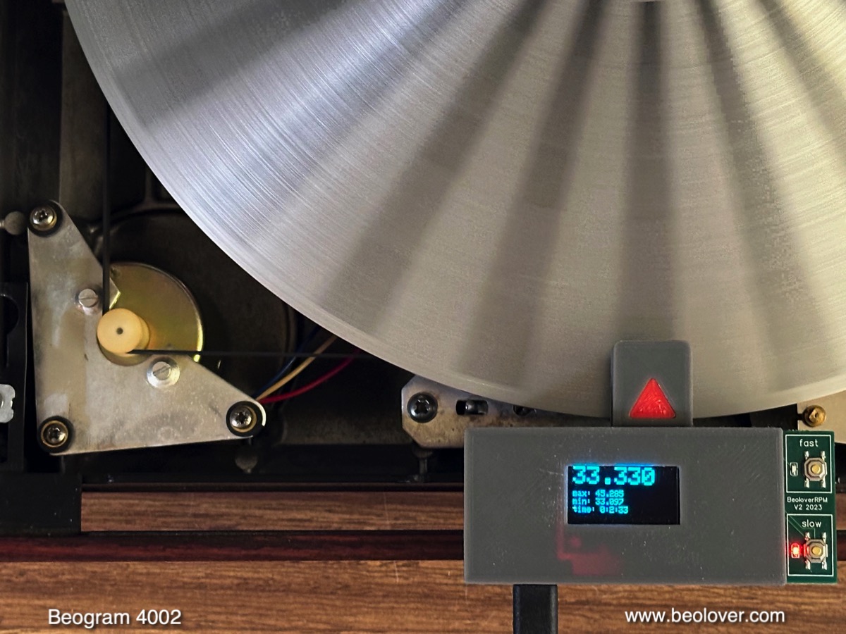
This is the curve I measured after about 24 hrs:

This curve is pretty much as good as it gets with DC motor Beograms. there is some longterm drift related to temperature changes (and possibly the moon phase...;-), but the changes are gradual and small enough that humans cannot discern them. This motor is back in business!
The BeoloverRPM has a second mode, 'fast', which measures the RPM every time a rib passes underneath the sensor. This allows 'wow and flutter' measurements, i.e. the measurement of short term variations of the RPM such as they occur when the motor feedback system regulates the platter speed based on the signal coming back from the pickup coils in the motor enclosure. The display of the device shows the last 64 measurement points in this mode:

As in the slow mode, the device can send the data to the serial port and it can be recorded for longer periods of time. This graph corresponds to about 60 platter rotations (~120sec):

The repeating pattern is a measurement artifact stemming from small manufacturing variations that cause the platter rib spacing to be slightly uneven around the platter. The pattern repeats every 24 measurement points, corresponding to the number of ribs around the platter. In essence this pattern represents a 'fingerprint' of a particular platter, and it is different for every Beogram. The sinusoidal variation of the pattern amplitude, however corresponds to real RPM changes that are caused by the feedback mechanism that works to keep the platter speed constant. This works based on a feedback signal that comes back from the motor and is fed into the control circuit. Whenever the motor runs a bit below the setpoint, the circuit increases the motor power until the motor runs slightly too fast. When the circuit receives the too fast feedback signal, it lowers the power until the motor runs a bit too slow and the process repeats. A well tuned feedback mechanism usually results in a sine curve like variation pattern around the setpoint. And that is what we can observe in the above curve. An evaluation of the changes yields a wow and flutter magnitude of about 0.1%, which is about 2x of the 0.05% number given on the specs page in the service manual. Most likely this discrepancy is a result of the different (analog) way these changes were measured back in the 1970s when this Beogram was designed. At any rate these RPM fluctuations are much too small to be audible to humans.
Next I replaced the original DIN5 plug with a modern all-metal type with gold plated contact pins. This shows the original plug:

This is the new replacement:

Beogolden!
On to installing the two upgrades my customer selected: The Beolover SyncDrive DC motor replacement and the Beolover Commander remote control system.
Before the installation of the Commander auto-repeat indicator under the CD4 indicator 'window' in the RPM panel above the keypad, I replaced the cracked original plexiglass parts that the RPM panel clicks into. They are often damaged from pushing the panel in at an awkward angle or less-than-careful extraction. In this Beogram they were in the early stages of deterioration:


A very nice reproduction of this part is available from the Beoparts-shop in Denmark. All that is needed for their installation is to move the metal clips over from the original parts. This shows old and new next to each other:

I put them in and then implanted the Commander remote control system. Here you can see it installed (plug and play, no soldering required). The auto repeat indicator is bolted to the keypad screw between the two new RPM panel clips:

Next came the installation of the SyncDrive. It is also a plug and play upgrade, no soldering required. It uses the same mounting posts as the original motor.

The SyncDrive upgrade was not really necessary for this Beogram since the original motor emerged in perfect condition from the restoration process. But the SyncDrive has a much better longterm RPM stability due to its more temperature-stable digital control system, and so it is still an improvement!
This gives an impression of both upgrades together:

And with platter installed:

And then it was finally time for a first test spin! I selected one of my favorite Bob James records, "Lucky Seven" that he recorded in 1979 for Zappan Zee Records (JC 36056). A perfect contemporary record for a Type 5523 Beogram 4002! Of course this lovely record was ultrasonically cleaned on a CleanerVinyl ProXL setup to restore its original glory!
Here is an impression of this perfect combination!:

I will now play this Beogram for another week or two, and if nothing else comes up it will be time to send it back to its original owner in Montana (for another ~50 years of service!...;-).
No comments:
Post a Comment
Comments and suggestions are welcome!