This post describes the restoration work done on a Beogram 4002 that I recently received from a customer in Kentucky. My initial assessment of the unit is posted here.
This shows the unit with the aluminum panels and platter removed:

It is in very nice original condition and has only very minor cosmetic flaws. A perfect candidate for a full restoration.
As usual with DC motor Beograms I started with the platter motor. They usually have dry motor bearings which results in RPM instabilities. This shows the extracted motor:

I took it apart to get the bearings out:

The bearings are the two small donuts on the black pad upfront. I immersed them in motor oil and pulled a vacuum:

Immediately strong bubbling started. This is indicative of air being drawn from the porous Oilite bearing material. The resulting vacuum inside the material encourages oil to enter into the material. This process usually takes about 48 to 72 hours. Once the bubbling stops the process is complete and the pores are full with oil again.
While this was going on, I focused on the other restoration tasks.
First I rebuilt the arm lowering and carriage transport mechanisms. This shows the original condition of the setup:

I removed all participating parts:

This shows them ready for ultrasonic cleaning:

After about an hour in the cleaner they looked nice and clean again:

Next came re-assembly. As usual, I replaced the rubber gasket in the damper assembly with a new one.

The original gaskets are often hardened and do not seat properly anymore. This causes inconsistencies in the arm lowering speed. This shows the setup after re-assembly:

I also replaced the original cracked plastic carriage pulley with a nice new precision machined aluminum reproduction:

Then I replaced the original incandescent bulb in the tracking sensor with a Beolover LED assembly. This shows the original setup. The bulb is in the black housing:

I removed the housing, which revealed the tracking sensor aperture:

This shows the original bulb assembly in direct comparison with the LED based replacement:

The LED is in the same spot like the bulb filament. I installed the new LED assembly:

The small white 'box' ontop of the assembly is a trimmer that allows adjusting the brightness of the LED. This can be helpful when calibrating the tracking feedback sensitivity.
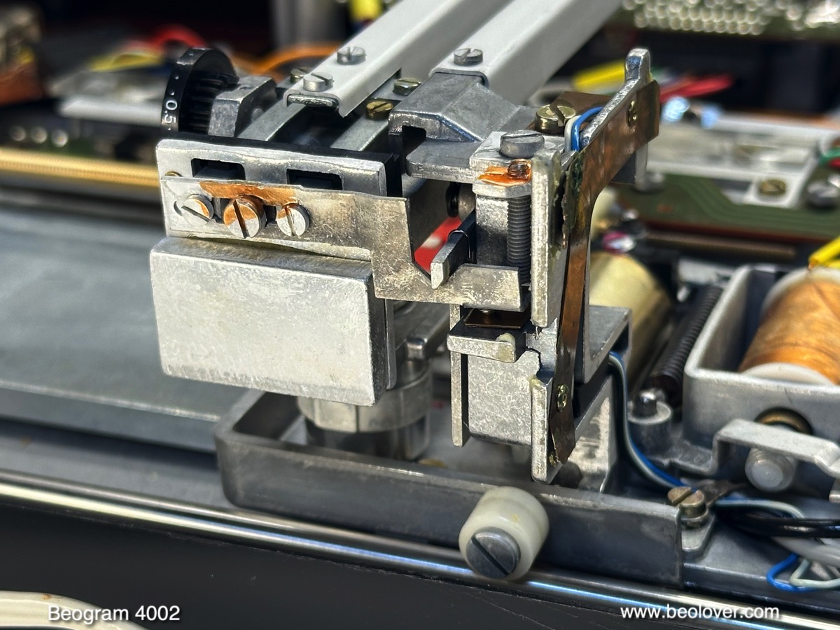
Then it was time to complete the work on the carriage by re-lubricating the damper to arm linkage. This linkage is mounted to the sensor arm assembly. In this picture you can see it stick out from the V-cut in the piece bolted to the back of the tonearm counter weight:
I removed the sensor arm and then took out the linkage:

As usual the small copper plate that helps the arms slide laterally while in up position came off after tugging on it lightly with my tweezers. I cleaned off the degraded double sided tape that holds it in place and epoxied it back into place. After cleaning and re-lubricating the pivot point of the linkage I re-assembled everything. This concluded my work on the carriage.
Now it was time for restoring the electronics. It is best to replace the two againg power Darlingtons that are mounted on the solder side of the main PCB before unbolting it. This ensures that the replacements are soldered in with the correct orientation.
This shows the original TIP120 (1IC1), which is responsible for regulating the 21V power rail:

I usually replace it with a stronger TIP102. For some reason, modern TIP devices can develop a high frequency oscillation superimposed to their output in this circuit configuration, which can confuse the record detection function. This can be alleviated by installing a 100nF capacitor between emitter and ground (small yellowish component in the picture):

After also replacing the other Darlington (1IC4) with a TIP107 I removed the board. This shows it in its original condition:

A detail shot of the 'RPM section', consisting of RPM relay and two RPM trimmers (left front corner):

I replaced all electrolytic capacitors, power transistors, RPM relay and trimmers and the sensor arm transistor and its bias resistor:

A detail picture of the rebuilt RPM section with a Beolover Siemens relay replacement and two modern 25-turn trimmers:

Next I removed the keypad to get to the output PCB:

I replaced the output relay and the electrolytic capacitor that is responsible for defining the time delay for activating the relay after the needle drops:

I also installed a (red) switch that allows connecting system and signal grounds, incase there is a hum when connecting the Beogram to an amplifier.
Then I removed the original reservoir capacitor. This Beogram 4002 was setup for accepting a CD4 pre-amplifier board, and so had a dual capacitance reservoir capacitor installed. This shows the original unit:

By now pretty much everything had been removed from the enclosure except the floating chassis. I disassembled the transport locks, which needs to be done before one can remove the floating chassis. This revealed beautifully degraded transport lock bushings:

After taking out the floating chassis a lot of debris from the transport locks could be seen:

This debris often hinders the floating chassis from swinging freely, and so needs to be removed before proper vibration dampening can be restored again. After vacuuming out the enclosure, I installed new Beolover transport lock bushings:

These bushings are designed for easy installation: Simply insert one half from the bottom

and the other from the top into the orifices in the floating chassis:

Then the chassis can be re-installed and the locks re-assembled:

After putting the chassis back in, I installed a new Beolover reservoir capacitor assembly:

It is a direct replacement of the entire dual-capacitance setup, including the rectifier.
After re-installing the main PCB, I adjusted the bias voltage of the transistor that amplifies the record sensor signal to yield 4V at the collector:

Then I moved the bias trimmer over to the component side of the board.
The next step was replacing the incandescent light bulbs in the RPM panel above the kaypad. This shows the panel removed and flipped over:

The bulbs are behind the two bulb covers. I removed the covers:

Then I unsoldered the bulbs. This shows the bulbs removed and the new Beolover LED assemblies ready for installation:

They solder directly to the solder pads of the bulb wires:

This shows one of the LED assemblies in detail. They essentially form an extension of the origina circuit board:

The bulb covers can be replaced after installation. The LED boards do not interfere with them:

This shows one of the LED boards in action:

They emit a nice incandescent-like light. The final bulb that needed replacing was the one in the sensor arm. It sits in the small insert in the sensor arm end. It can be pulled out:

The above picture shows the bulb still in place together with the Beolover sensor arm LED assembly ready for installation. I removed the bulb and installed the LED assembly:

This shows it in action. The LED emits warm white light with enough red photons to be able to light up the B&O logo at the end of the arm properly:

Now it was time to do the mechanical adjustments. Like most Beograms that I get on my bench the arm to platter distance was off and the arms were not parallel to the platter either. So I did this adjustment first, followed by an adjustment of the floating chassis to get the platter flush with the surrounding aluminum panels. Once this was squared away, I was able to do the arm adjustments. First I calibrated the tracking force. I usually install a square M3 nut to replace the flimsy retining washer that holds the counter weight adjustment screw in place:

This allows locking the counterweight calibration into place that it can survive the rigors of shipping. I usually try to calibrate the small scale on the tracking weight adjusting wheel that it is correct around 1.2g, which is the tracking weight that most B&O cartridges need:

There is one more important arm related adjustment: The arm lowering limit. If adjusted correclty, the needle will miss the lower portions of the ribs by about 1 mm:

This is an important safeguard in case the record detection circuit malfunctions and the arm is lowered on an empty platter.
Next came the adjustment of the tracking feedback:

In the meantime the bearing infusion process had come to an end and the bubbling had stopped. I broke the vacuum and extracted the restored bearings from the oil:

Then I re-assembled the motor with the freshly infused bearings. I also installed a new Beolover DC motor pulley to replace the original pulley, which showed first signs of damage from contact with a decaying belt:


Looks like new! Beolovely!
And with that it was time to measure the RPM stability of this restored motor with the BeoloverRPM device:
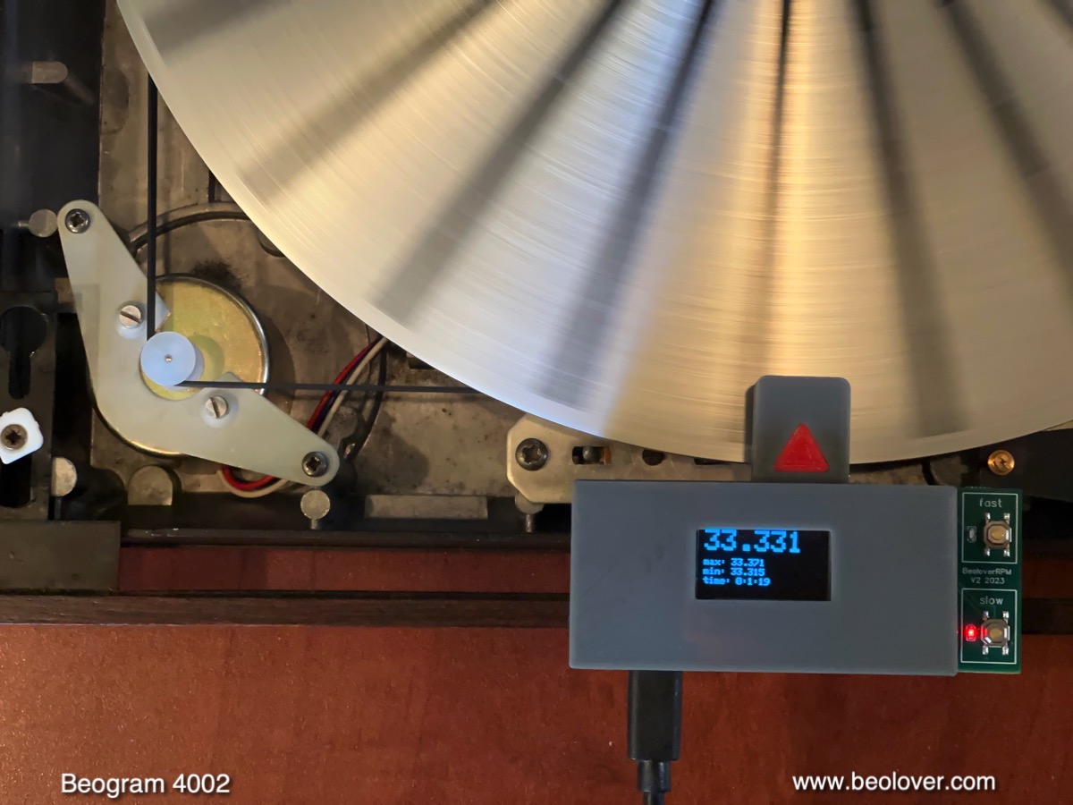
In its 'slow' mode the BeoloverRPM allows logging the RPM in 10s intervals, which is a great way to confirm any RPM inconsistencies that would otherwise be difficult to detect by just listening to records. This is the curve I measured after about 24 hrs:

This is pretty much as good as it gets with DC platter motors. With these motors there is always some long-term drift, usually caused by thermal effects. A normal characteristic of analog control systems. The little upward bump is probably related to the upper motor bearing getting polished by the shaft in its new position. Overall, these RPM changes are happening pretty slowly, and they are on a magnitude that is impossible for humans to discern. This motor is ready for duty again!
Next, I ran the BeoloverRPM in its 'fast' mode to get a reading on 'wow and flutter', i.e. RPM changes on a short time scale. This shows the BeoloverRPM in action:

In the fast mode a RPM measurement is recorded each time a platter rib passes under the sensor. This generates high-resolution RPM data that looks like this:

This graph covers about 60 platter rotations, or about 120 sec. of runtime. The interesting pattern is a convolution of real RPM changes and a measurement artifact that is a result of the very slightly irregular spacing of the platter ribs around the platter. On closer inspection, the zig-zag pattern is repeated every 24 measurement points (there are 24 ribs...) and can be regarded as a 'fingerprint' of a particular platter. It turns out that each Beogram platter has a distinct pattern due to manufacturing tolerances when the slots were machined for the black rubber ribs.
The overlaid wavy pattern, however, reflects real RPM changes that are introduced by the feedback based control system that keeps the motor RPM constant. An evaluation of this wave pattern yields a wow and flutter percentage of about 0.1%. The service manual lists 0.05% as the spec for the DC platter motors, but this 2x difference may well be related to the different way this was measured in the 1970s in absence of modern microcontrollers. At any rate this difference is pretty academic since it is much to small to be discernible.
After this successful measurement I replaced the original DIN5 plug

with a modern all-metal plug with gold plated contact pins:

And then it was finally time for a test-spin!
I selected "Cherry", a very lovely CTI vinyl (CTI 6017) from 1972 by Stanley Turrentine and Milt Jackson. Of course this record was ultrasonically cleaned using a CleanerVinyl ProXL setup to restore its original lush sound. CTI pressings are usually pretty good quality and ultrasonic cleaning takes care of most clicks and pops.
A perfect record to play on this fully restored Beogram 4002!

I will now play this Beogram for a while to make sure there are no intermittent issues, and then it will be time to send it back to its owner!
Not so quick! After playing a few sides I realized that the up/down key on the keypad was intermittent. Once in a while it would work and often not. So I removed the aluminum panels again and had a look. It turned out that the wire from the key to the PCB plug was intermittent. I removed the keypad PCB and had a closer look:

I extracted the yellow wire that connects the up/down key and after I pulled the contact terminal from the plug shell, it became immediately clear:

The wire was not properly crimped. An easy solution in such cases is to simply put a dab of solder on the crimp, and that is what fixed it:

After reassembling, up/down worked perfectly. On to installing all Beolover upgrades, i.e. SyncDrive, Commander remote control and internal RIAA pre-amp. Read about it here!
No comments:
Post a Comment
Comments and suggestions are welcome!