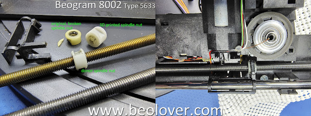
I began the restoration of this Beogram 8002 turntable with the floating chassis components.
The main reason for that is two broken parts I discovered during the initial assessment.
I wanted to tackle those two (key) problems first because I wanted to make sure they could be properly fixed.
For the spindle nut with a broken guide wall for the bracket that connects it to the tangential arm assembly...I decided to go with a spare (or donor) spindle nut from my box of Beogram 800x turntable parts.
In the case of the broken tab that secures the Beogram 8002 position sensor assembly...I had to design a 3D printed part that would properly secure the broken tab and still allow the tab to let the sensor assembly board be removed.
It took some modification of my initial design but I finally achieved what I was after.
The 3D part glues onto the molded plastic that comes with the Beogram floating chassis.
The broken, plastic tab is also glued to the 3D part and the area of the chassis it broke off from.
The ends of the 3D part wrap around the chassis base on all four sides to provide strength.
The end closest to the servo motor has to have a slot for the sensor assembly.
The 3D part wall on the spindle side had to be made smaller than I originally designed it to leave room for the sensor wheel and to attach/remove a rubber belt.
Here is another view.
While I had the floating chassis components where they are still easily accessible, I decided to perform a few Beogram 8002 adjustments that involve the tangential arm assembly.
To do this I removed the spindle assembly and just left the arm assembly on the two rails.
This allowed me to manually slide the tangential arm assembly wherever I wanted to without manually rotating the spindle (which gets old fast). I also didn't want to wait until the electronics were completed and working...then take the arm assembly out again.
With this setup I adjusted the height of the fixed-arm (sensor arm) relative to the top of the platter.
The distance per the service manual is 19.5 mm (different than the Beogram 8000 and Beogram 400x turntables).
With the fixed-arm height set per the service manual the next adjustment is to make the top of the tonearm match the top of the fixed-arm.
The adjustment screw for the tonearm height is underneath the tangential arm assembly so you can see why I want to get it out of the way first and not come back to it.
I am not showing the phono cartridge tracking force calibration here but I did do an initial calibration of the tracking force counter-weight, phono cartridge and force selection slider while I had the floating chassis components apart. I will do a final check later when the Beogram is assembled for testing.
Next, I cleaned and applied rubber cleaner/treatment to the two damping rubber inserts on the rear tangential arm rail.
Note that the rubber dampers are only on the rear rails of Beogram 8002 turntables used with 60 Hz line voltages. They aren't necessary where the line voltage is 50 Hz.
The last floating chassis component tasks I worked was to replace the audio muting relay and the two capacitors on the +5 VDC regulator.
Here is the muting relay replacement.
Note that the Beogram 8000 has a different muting relay.
Here are the only two floating chassis mounted electrolytic capacitors that get replaced.
The next post for this Beogram 8002 project will focus on the main electronics restoration work.


No comments:
Post a Comment
Comments and suggestions are welcome!