I pulled the output amplifier assembly back out of the Beomaster 8000 cabinet so I could test it stand-alone on the bench.
That removal procedure is getting easier to perform but it is still not a fun task.
Here is the left channel output amplifier assembly with the connections to test it.
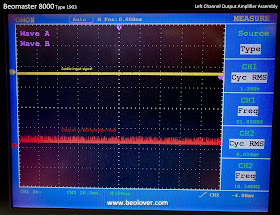
Here are the voltages and the input/output signals when the output amplifier assembly is power up without any input signal. The oscilloscope shows just a flat line for the amplifier output to the speaker load.
I used an HP 8903A audio analyzer to supply the test sine wave signal. This was a 1KHz sine wave with an amplitude I adjusted from 0.0 Vrms to around 20mVrms.
Here is the starting point (0.9mVrms, 1KHz sine wave).
Here is the output with a 20mVrms, 1KHz waveform applied at the audio input to the board.
The output signal looks bad. Compare that to a spare, good Beomaster 8000 output amplifier board.
This Beomaster 8000 left channel output amplifier assembly needs more work.


No comments:
Post a Comment
Comments and suggestions are welcome!