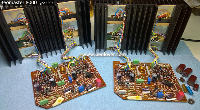
The two output amplifier boards for the Beomaster 8000 from Texas are now rebuilt. That gives me two sets of Beomaster 8000 amplifier boards to bench test.
These two (left and right) output amplifier boards are more typical of what I find on a Beomaster 8000 restoration. There are some very distinct darkened areas on the component side of the board caused by heat coming off the board components.
I started with the right channel board. No particular reason as both boards are identical.
I like to be methodical and work one board at a time and one side of the heatsink mounted components at a time. That is safer in preventing mistakes as I have the other output amplifier assembly to refer to.
Here is the heatsink with the PNP Darlington transistors removed.
It looks nice and clean but the job never gets any easier regarding the messy old thermal paste cleanup.
I installed the right side (PNP Darlingtons - 5IC204, 5IC205, 5IC206) on their Sil-pads and then worked the left side (NPN side - 5IC201, 5IC202, 5IC203).
There is one small place I still use some thermal paste and that is where the PTC resistor fits on the heatsink.
Although the right side of the heatsink assembly mounts the three PNP Darlingtons (5IC204, 5IC205, 5IC206) it does have one NPN transistor (5TR208 - BD135).
Now for the output amplifier board. I replaced the six electrolytic capacitors and two trimmer resistors. I also took the opportunity to clean all of the old dust and grime off the board so it looks as close to new as I can get it.
Before
After
While the wires from the heatsink components were disconnected from the output amplifier board I measured the transistors to verify they were still good. The transistors measured good and I reconnected the wires. As for the electrolytic capacitors, this right channel board had several that were completely shot and the others were out of tolerance.
On to the left channel output amplifier board.
Like the right channel it had quite a bit of grime and dust.
The heatsink mounted transistors all checked out and the electrolytic capacitors still had capacitance...but almost all of them were out of tolerance.
Here is the cleaned up board with its new components.
I saved the messy heatsink mounted component task for last on this one.
Here is the right side cleaned and prepared.
...and here are the left and right channel boards completed and ready to be tested.
Beolover provides professional Bang&Olufsen maintenance and restoration services. We give one year warranty on parts and labor. All parts featured on the blog are also available to other enthusiasts for their restoration projects. Please, send an email to beolover@gmail.com or use the contact form on the side bar. Enjoy the blog!
Featured Post
Beolover SyncDrive: DC Platter Motor Replacement for Beogram 4002 and 4004 (Type 551x and 552x)
Late Beogram 4002 and the 4004 (Types 551x and 552x), which have DC platter motors instead of the earlier synchronous AC motors usually suff...
Subscribe to:
Post Comments (Atom)


No comments:
Post a Comment
Comments and suggestions are welcome!