Every nook and cranny has some piece of debris in it.
Even the tangential arm assembly didn't escape the spread of the bushing debris.
Eventually I got everything cleaned up.
Next I decided to start in on the electrical restoration. The first thing is the power reservoir capacitor that mounts to the chassis. I am replacing the original 4000uF capacitor with a Beolover replacement that includes a 3D printed housing so it can mount with the capacitor mounting bracket.
The custom part makes this installation a breeze and professional.
Now for the Beogram 4004 main board. It has a lot of blue tantalum capacitors that need replacing and a few electrolytic capacitors I will also replace. For values 4.7uF and less I like using WIMA polyester capacitors. They are non-polar and last a long time. In a couple places where the larger 4.7uF WIMA capacitors don't fit, I will use Nichicon 4.7uF electrolytic capacitors.
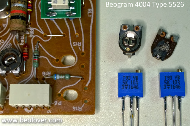
This board will also get three trimmer resistors replaced: the 33 RPM adjustment trimmer, the 45 RPM adjustment trimmer and the calibration trimmer for the photo darlington adjustment. That is the sensor for the tangential arm transport position.
I will also replace the RPM speed select relay with a Beolover custom replacement relay module.
Here is the main board prior to the restoration work.
These next pictures show the new Beolover RPM relay and the trimmers that were replaced.
Here is the finished main board.
Next up is the small output board.


No comments:
Post a Comment
Comments and suggestions are welcome!