I moved the Beomaster to my test bench and began measuring the voltages from the power supply.
Starting with the ±15 VDC regulators and the 5 VDC regulator, everything testing out good.
Here are pictures of those measurements.


The next check was the ±55 VDC voltage rails for the left and right channel output amplifiers. Those also measured good.


This is a nice milestone for the project to have the Beomaster 8000 powered on and the voltages all verified. Now it is time to adjust the no-load idle current and DC offset voltage of the left and right channel output amplifiers. This is a must do. Especially before connecting up any speakers.
The service manual describes the No-Load Current Adjustment here -

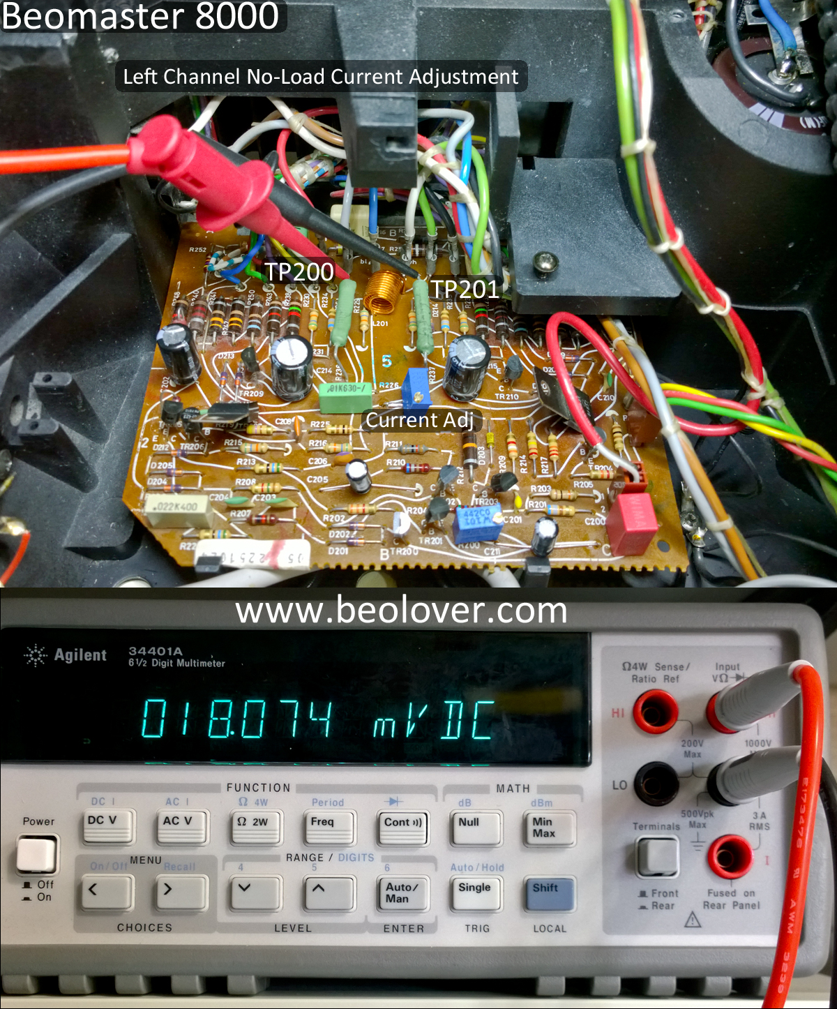
The method I use is option 1 - To measure 18mVDC across TP200 and TP201. The 18mVDC measurement is to be made right as the Beomaster is powered on (before it is fully warmed up).
Here is a picture of the left channel adjustment (the right channel board is identical).
After the no-load current adjustment the service manual shows the DC offset adjustment.

This is also an easy adjustment to hook up for. I attach my DVM leads to the Speaker 1 terminals and turn on the Speaker 1 switch (no speakers are connected at this point though).
The other Bourns trimmer I installed is the one that controls this adjustment. It can be seen in the lower left of the picture.

After the Beomaster was left on for a while I re-adjusted the left and right DC offset again to as low as I could get it.

Now for a real world test. I connected up a pair of Beovox S55 speakers I keep in my workshop and connected an FM antenna to the Beomaster.
It has sound -

The next part of the test drive I turned on the filters (bass & treble) for the Beomaster and connected an iPod Nano to the TP2 input. I also cranked the volume up.

The Beomaster sounds great. This is such a favorite receiver of mine.
Remember that in my pre-restoration testing of this Beomaster it would only play for a short amount of time before stopping. So far I have been playing music through this receiver for over an hour without a hiccup. It would appear the problem it was having was related to power.
I will leave the Beomaster playing for a few more hours to make sure. After that it will be time to move on to the last few boards for recapping, replacing the old displays with SMD LED devices and finding a damper for the control panel lid. Then this Beomaster will be ready to be returned to its owner.
No comments:
Post a Comment
Comments and suggestions are welcome!